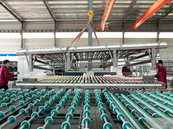
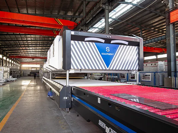
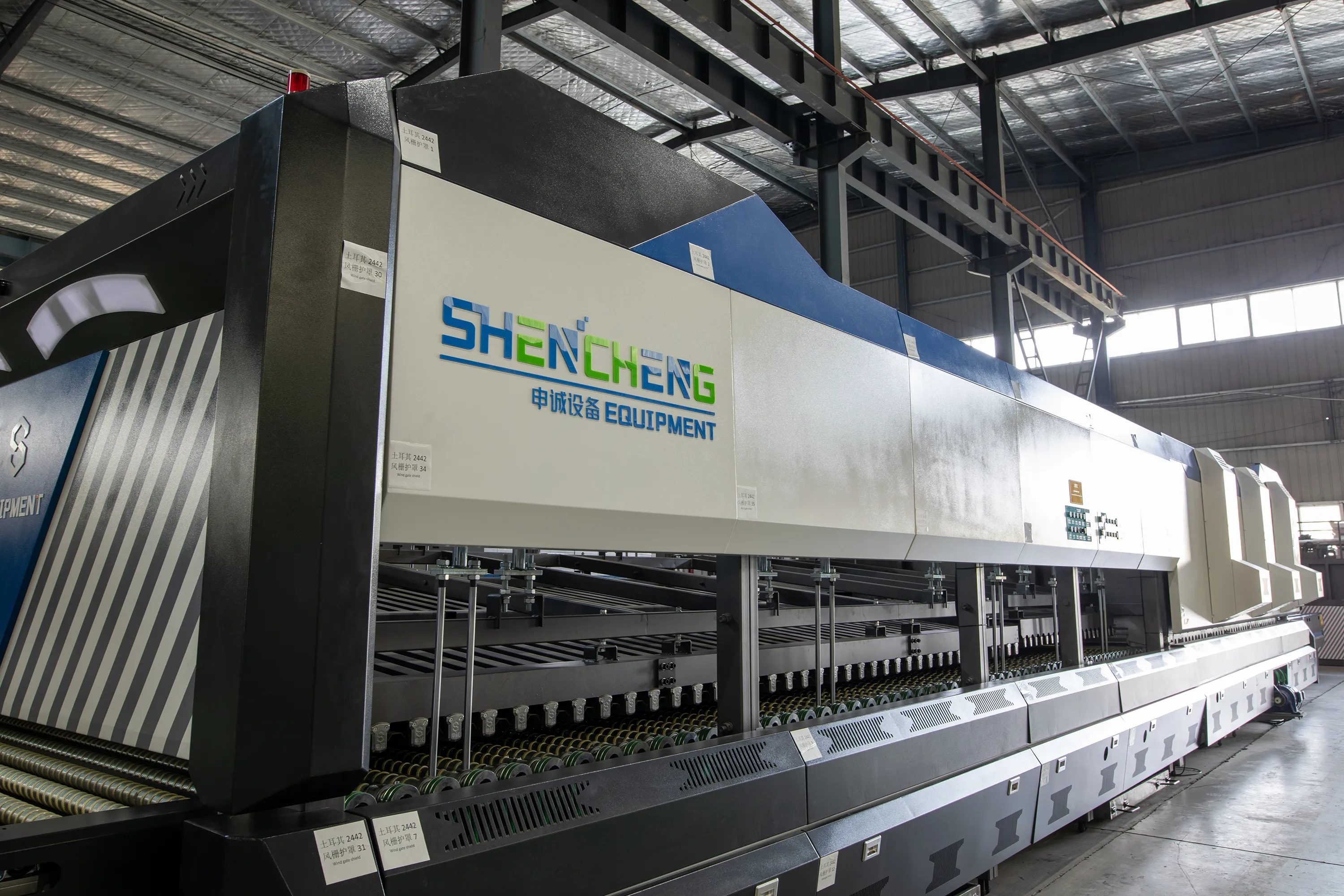
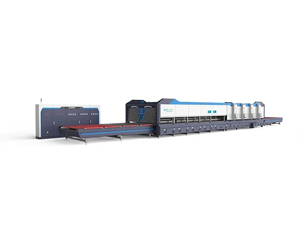
The price of a glass tempering furnace can vary widely based on several factors, including the type, size, and specifications of the furnace, as well as the brand and additional features it may have. Here’s a breakdown of the factors affecting the price:

Factors Affecting the Price of a Glass Tempering Furnace:

glass tempering furnace

Type of Furnace:

Horizontal Tempering Furnace: More commonly used and typically more expensive due to its advanced technology and versatility in handling different glass sizes and thicknesses.

Vertical Tempering Furnace: Usually cheaper but less versatile and often used for smaller-scale operations or specific types of glass.

Size and Capacity:

The size and capacity of the furnace directly impact its cost. Larger furnaces capable of tempering bigger glass sheets or higher volumes will generally be more expensive.

Heating Method:

Furnaces with more advanced heating methods, like forced convection heating or radiation heating, may cost more due to increased energy efficiency and faster heating times.

Brand and Manufacturer:

Reputable brands with a track record of quality, reliability, and customer support often come with a premium price. However, they may offer better warranties and after-sales service.

Customization and Features:

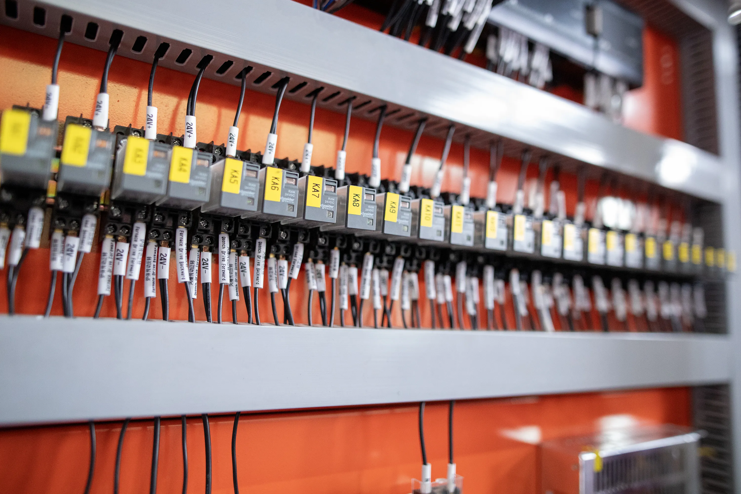
Custom features such as automated loading/unloading systems, advanced control systems, specialized cooling systems, or energy-efficient components can increase the cost.

For more detailed information about glass tempering furnace prices, please click here: https://www.shencglass.com/en/a/news/tempering-furnace-price.html

The electricity consumption of a glass tempering furnace varies widely depending on several factors, such as the furnace size, type (horizontal or vertical), efficiency, the thickness and type of glass being processed, and production capacity. However, here are some general estimates:

Glass tempering furnace hourly power consumption

Small Glass Tempering Furnaces: These can consume anywhere from 50 to 200 kWh per hour.

Medium Glass Tempering Furnaces: These typically consume between 200 to 500 kWh per hour.

Large Industrial Glass Tempering Furnaces: These can consume upwards of 500 to 1000 kWh or more per hour, depending on their size and capacity.

Factors Affecting Electricity Consumption of a Glass Tempering Furnace

glass tempering furnace

Furnace Size and Type:

Small Furnaces: Usually consume between 50 to 200 kWh per hour.

Medium Furnaces: Typically consume between 200 to 500 kWh per hour.

Large Furnaces: Can consume 500 to 1000 kWh or more per hour.

Type of Furnace: Horizontal furnaces generally consume more electricity compared to vertical furnaces due to differences in heating mechanisms and loading processes.

Glass Thickness and Type:

Thicker glass requires more heating time and energy, leading to higher electricity consumption.

The type of glass (e.g., low-emissivity, laminated, or tinted glass) may also affect heating requirements.

Production Capacity and Batch Size:

Higher production capacities and larger batch sizes typically result in higher energy consumption due to increased heating and cooling requirements.

For more detailed information about the hourly power consumption of glass tempering furnaces, please click here: https://www.shencglass.com/en/a/news/glass-tempering-furnace-hourly-power-consumption.html

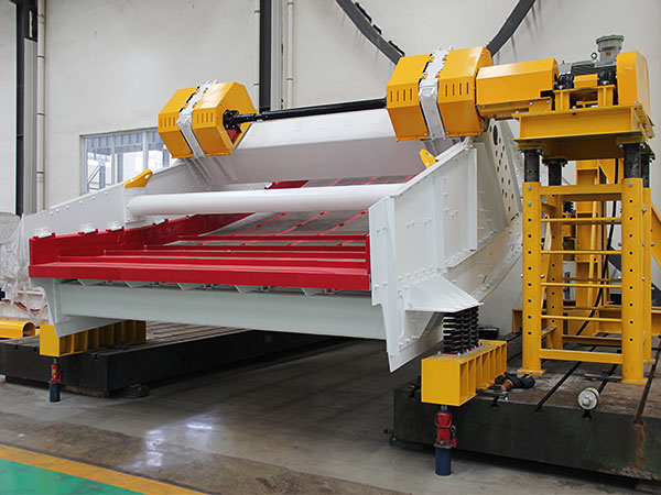
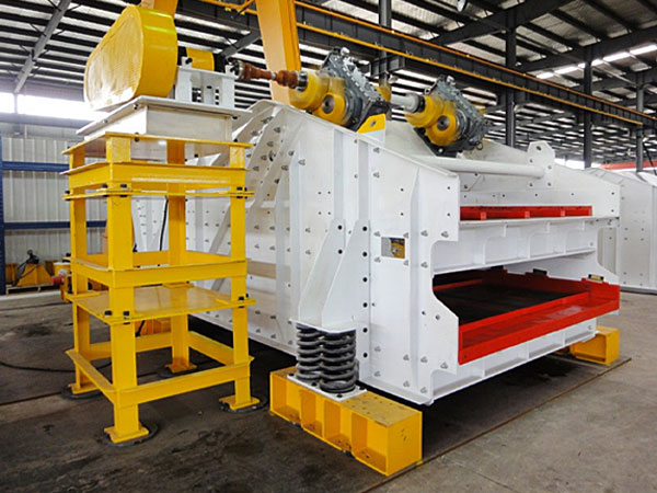
Linear vibrating screens are widely used in various industries for the separation and classification of materials. They operate on the principle of a linear motion, utilizing two vibrating motors that create a linear motion along the screen.

A circular vibrating screen is a type of screening equipment used to separate materials based on size.

The difference between linear vibrating screen and circular vibrating screen

Linear and circular vibrating screens are both used for sorting and separating materials, but they have different operational principles and applications.

Linear Vibrating Screen:

Movement: The screen moves in a straight line, creating a linear motion.

Design: Typically has a rectangular or square shape.

For more detailed information about the difference between circular vibrating screen and linear vibrating screen, please click to visit: https://www.zexciter.com/en/a/news/the-difference-between-linear-vibrating-screen-and-circular-vibrating-screen.html

Vibration motors are devices that generate mechanical vibrations for a variety of applications, such as haptic feedback in devices, industrial machinery, and consumer electronics. There are several types of vibration motors, each with distinct characteristics, designs, and applications.

Types of Vibration Motors

Vibration motors

Eccentric Rotating Mass (ERM) Motors

Description: ERM motors are DC motors with an unbalanced weight attached to the shaft. When the motor rotates, the centrifugal force generated by the offset weight causes the motor to vibrate.

Applications: Widely used in mobile phones, pagers, wearable devices, and other small handheld gadgets for haptic feedback.

Advantages: Simple design, cost-effective, easy to control the vibration intensity by varying the speed of rotation.

Disadvantages: The vibration is not uniform due to the rotating mass.

Linear Resonant Actuators (LRA):

Description: LRAs consist of a magnetic mass suspended by a spring, which oscillates when an AC signal is applied. They are tuned to resonate at a specific frequency, providing a strong vibration at a particular resonance.

Applications: Used in smartphones, tablets, gaming controllers, wearables, and other devices requiring precise haptic feedback.

Advantages: Faster response time, better energy efficiency, and more precise control over vibrations than ERM motors.

Disadvantages: More complex control circuitry is required, and they are typically more expensive than ERM motors.

Coin Vibration Motors:

Description: These are a type of ERM motor that is flat and coin-shaped. The eccentric mass is embedded in a circular housing, making it compact and easy to integrate into slim devices.

Applications: Commonly used in portable devices like smartphones, smartwatches, and fitness bands.

Advantages: Compact size, low power consumption, easy to mount.

Disadvantages: Limited vibration strength due to their small size.

Vibration motors

Brushless DC Vibration Motors:

Description: These motors use a brushless DC motor design, where the rotation of a magnet induces vibration without physical brushes. The vibration mechanism is similar to ERM but with higher efficiency and durability.

Applications: Industrial equipment, automotive applications, and more demanding environments requiring long life and reliability.

Advantages: Longer lifespan, lower maintenance, higher efficiency, and better control.

More detailed information about vibration motor types can be found at: https://www.zexciter.com/en/a/news/vibration-motors-types.html

Vibrating feeders are devices used to feed bulk materials continuously and uniformly to processing machines or conveyors. They are widely used in industries such as mining, metallurgy, coal, construction, chemical, and food processing. The specifications and models of vibrating feeders vary depending on the application, material to be handled, and desired capacity.

Specifications of Vibrating Feeders

Vibrating feeders

Capacity:

The capacity of vibrating feeders ranges from a few tons per hour (tph) to several hundred tph. Common capacities include 10, 50, 100, 200, and 500 tph, depending on the model and application.

Size of the Feeder Deck:

The width and length of the feeder deck can vary. Typical widths range from 300 mm to 3,000 mm, and lengths range from 600 mm to 6,000 mm.

Feeder Type:

Electromagnetic Vibrating Feeders: Ideal for smaller volumes and precise feeding applications.

Electromechanical Vibrating Feeders: Suitable for handling larger loads and for heavy-duty applications.

Grizzly Vibrating Feeders: These feeders have grizzly bars for separating fines and are used for handling materials with large lump sizes.

Vibration Frequency and Amplitude:

Frequency usually ranges from 750 to 3000 vibrations per minute.

Amplitude varies from 1 mm to 15 mm, depending on the material flow and feeder design.

Motor Power:

Motor power ranges from 0.5 kW to 15 kW or more, depending on the feeder size and capacity.

Material of Construction:

Made from various materials, such as carbon steel, stainless steel, and high-strength alloys, depending on the application and material to be handled.

Installation Type:

Available in stationary, mobile, or portable configurations depending on the setup and use.

For more detailed information on the specifications and models of vibrating feeders, please click here: https://www.zexciter.com/en/a/news/vibrating-feeder-specifications-and-models.html

A gantry welding machine is a type of welding equipment that uses a gantry structure to support and guide the welding head or torch along a workpiece. It is commonly used in automated welding processes for large, heavy, or complex structures, such as shipbuilding, bridge construction, steel fabrication, and large-scale industrial projects.Operating a gantry welding machine involves following a set of detailed procedures to ensure safe and efficient operation. Below is a general guide for operating a gantry welding machine.

Gantry Welding Machine Operating Procedures Guide

Gantry Welding Machine

1. Pre-Operation Inspection

Safety Gear: Ensure that you are wearing appropriate personal protective equipment (PPE), such as welding gloves, helmet with a proper filter lens, safety goggles, ear protection, and flame-resistant clothing.

Machine Condition: Inspect the welding machine for any visible damage or wear. Check for loose bolts, damaged cables, or any signs of leaks.

Check Electrical Connections: Ensure all electrical connections are secure, and there are no exposed wires.

Inspect Welding Consumables: Check the condition of the welding wire, electrodes, and flux. Replace or refill if necessary.

Test Gas Supply (if applicable): Ensure the shielding gas cylinder is properly connected, and the flow rate is set to the required level.

2. Machine Setup

Position the Gantry: Align the gantry in the desired position along the welding track or workpiece.

Secure the Workpiece: Properly clamp and secure the workpiece on the welding table or fixture to avoid movement during welding.

Adjust Welding Parameters: Set the welding current, voltage, speed, and other parameters according to the material type, thickness, and welding method (MIG, TIG, Submerged Arc Welding, etc.).

Set the Welding Torch: Position the welding torch or head at the correct distance and angle to the workpiece.

Gantry Welding Machine

3. Operation Start-Up

Power On the Machine: Turn on the main power supply and the welding machine.

Select Program or Mode: Choose the appropriate welding program or mode (manual, semi-automatic, or fully automatic) as per the job requirements.

For more detailed information about the gantry welding machine operation procedures, please click here: https://www.bota-weld.com/en/a/news/gantry-welding-machine-operation.html

An electricity power pole welding line is a specialized production line used for manufacturing electricity power poles, typically made from materials like steel or concrete.The process flow of an electricity power pole welding line typically involves several key steps.

Electricity power pole welding line process flow

electricity power pole welding line

1. Raw Material Preparation

Material Inspection: Check quality and specifications of incoming materials (steel or concrete).

Cutting: Use cutting machines to cut raw materials to required lengths for poles.

2. Component Fabrication

Forming: Shape the cut materials into the necessary profiles (for steel poles).

Drilling: Create holes for mounting brackets or other features as needed.

3. Welding

Assembly: Arrange the components in the correct configuration.

Welding: Use appropriate welding techniques (MIG, TIG, or submerged arc) to join the components securely.

electricity power pole welding line

4. Cooling and Stress Relief

Cooling: Allow welded sections to cool down naturally or use controlled cooling methods.

Stress Relief: Apply processes to relieve residual stresses if necessary.

5. Inspection and Quality Control

Visual Inspection: Check for visible defects in welds and overall structure.

Non-Destructive Testing (NDT): Perform tests like ultrasonic or radiographic inspection to assess weld integrity.

For more detailed information about the process flow of the power pole welding production line, please click to visit: https://www.bota-weld.com/en/a/news/electricity-power-pole-welding-line-process-flow.html

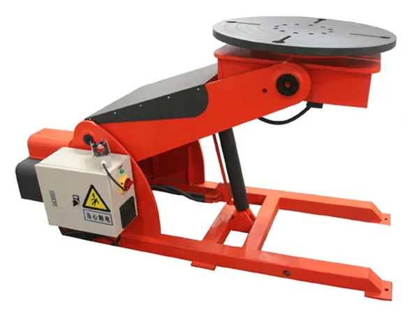
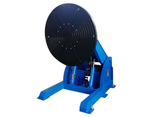
A welding positioner is a device used in welding and fabrication processes to rotate, tilt, or reposition the workpiece to an optimal position for welding. This allows for more efficient, safer, and higher-quality welding operations. Welding positioners are commonly used in various industries, including automotive, aerospace, shipbuilding, and heavy machinery manufacturing.

Functions of a Welding Positioner

Welding Positioner

Enhancing Welding Efficiency:

Welding positioners allow welders to perform welding tasks continuously without frequently stopping to adjust the workpiece. This reduces downtime and increases overall productivity by ensuring that the weld is performed in the most effective position.

Improving Weld Quality:

By positioning the workpiece in the ideal orientation, a welding positioner ensures that the welder can maintain a consistent welding speed, angle, and position. This results in more uniform welds, better penetration, and reduced weld defects.

Providing Optimal Welding Positions:

Positioners can rotate, tilt, or turn the workpiece to achieve the “downhand” or “flat” welding position, which is the most ergonomic and stable position for a welder.

This minimizes the chances of defects like slag inclusion and porosity.

Reducing Welder Fatigue:

Welders often have to work on large, awkward, or heavy components that are difficult to maneuver manually. Welding positioners reduce physical strain by automating the handling of the workpiece, allowing the welder to focus on the welding process itself. This leads to reduced fatigue and better safety.

Increasing Access to Difficult Weld Joints:

For complex assemblies or multi-axis welding, positioners can precisely orient the workpiece, providing better access to hard-to-reach joints or awkward weld angles. This allows for continuous welding on intricate components.

Supporting Heavy and Large Workpieces:

Positioners are designed to handle large and heavy workpieces that cannot be easily manipulated manually. They ensure stable support and safe positioning, minimizing the risk of workpiece slippage or falls.

Automating Welding Processes:

Welding positioners can be integrated with robotic or automated welding systems to create a more streamlined, automated welding process. This is particularly useful for repetitive or high-volume welding tasks, improving consistency and throughput.

For more detailed information about the welding positioner functions, please click here: https://www.bota-weld.com/en/a/news/welding-positioner-function.html

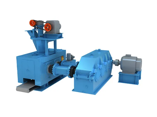
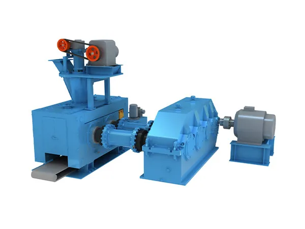
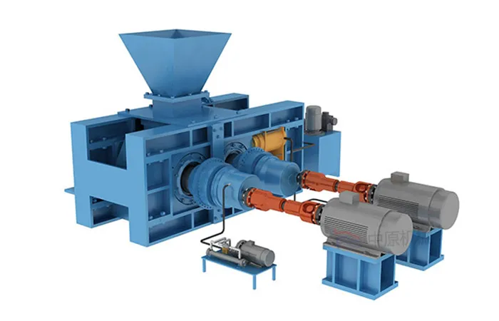
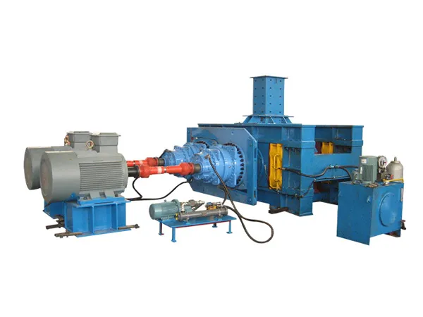
The high pressure grinding rolls is composed of two rollers, one of which is fixed and the other can slide horizontally. The material is continuously fed from the top and passes through the gap between the rollers. The movable roller is pressurized by hydraulic pressure, the material is crushed by pressure, and is pressed into cakes and falls out of the machine.

high pressure grinding rolls

High pressure grinding rolls may encounter a variety of common faults during operation. These faults and their solutions can be summarized as follows:

1. Abnormal vibration

Fault causes:

Uneven material size: Uneven material size will cause the extrusion force of the equipment to be unbalanced, causing vibration.

Severe wear of the scraper: The scraper cannot effectively shovel the material after wear, causing the roller to squeeze the material sometimes and sometimes not, causing vibration.

Too hard material: Too hard material may cause deformation and wear of the grinding roller and grinding ring, thereby aggravating vibration.

Fan problem: The fan blades of the high-pressure suspended shaft grinding fan accumulate too much powder or wear, causing unbalanced rotation of the fan blades.

Loose anchor bolts: After the equipment has been used for a period of time, the anchor bolts may loosen due to vibration or installation reasons.

Solution:

Adjust the particle size of the material and try to make it uniform.

Regularly check and replace worn scrapers.

Avoid processing of too hard materials, regularly check and replace grinding rollers and grinding rings, and remove metal debris from the material.

Remove the accumulated powder on the fan blades in time, and replace them in time if they are worn.

Pay attention to the tightness of the anchor bolts during daily maintenance. Tighten them in time if they are loose.

2. Powder discharge problem

Cause of failure:

Wear of shovel blade: Wear of shovel blade leads to reduced powder discharge.

Powder lock is not adjusted properly: The seal of powder lock is not tight, resulting in powder back-sucking.

Solution:

Check and replace worn shovel blades regularly.

For more detailed information about common faults and solutions of high pressure grinding rolls, please click to visit: https://www.zymining.com/en/a/news/common-faults-and-solutions-of-high-pressure-grinding-rolls.html

The internal structure of a cylindrical mixer is designed to facilitate effective mixing of materials, typically powders, granules, liquids, or combinations thereof. The exact internal structure can vary based on the mixer type and its intended application, but here is a general overview of the typical components found inside a cylindrical mixer.

Internal Structure of a Cylindrical Mixer

cylindrical mixer

Mixing Chamber (Cylinder Body)

The main component of the mixer, which is a cylindrical shell that houses all the internal mixing elements. It is usually made of stainless steel or other durable materials to withstand wear and chemical reactions.

Mixing Elements (Agitators)

Paddles or Blades: These are fixed to a central shaft that rotates inside the cylinder. The paddles or blades are shaped and angled to create a turbulent flow, ensuring effective mixing of materials. The design can vary from flat, helical, spiral, or ribbon shapes depending on the type of mixing required.

Helical Ribbon Agitator (for Ribbon Blenders): A double helical ribbon agitator is a common feature in ribbon blenders. It consists of an inner and outer ribbon that rotates to move material in opposite directions, creating a thorough mixing effect.

Central Shaft

The shaft runs along the center axis of the cylindrical chamber and is powered by a motor. The mixing elements (paddles, blades, or ribbons) are attached to this shaft. The rotation speed and direction can be adjusted based on the material properties and mixing requirements.

End Plates or Covers

The cylinder is enclosed by end plates or covers on both ends. These may have openings for loading and unloading the material, as well as access ports for cleaning, inspection, or maintenance.

Baffles or Deflectors

Fixed to the inner walls of the cylindrical chamber, baffles or deflectors disrupt the flow pattern and improve mixing efficiency by preventing the materials from rotating as a single mass (especially in high-viscosity mixing).

Discharge Port or Valve

Located at the bottom or side of the cylinder, the discharge port or valve is used to remove the mixed material from the chamber. The design of the discharge port can vary (e.g., butterfly valve, slide gate) depending on the viscosity and flow characteristics of the material.

Heating or Cooling Jacket (if applicable)

For processes that require temperature control, some cylindrical mixers are equipped with an external jacket that allows heating or cooling fluids to circulate around the mixing chamber. This helps maintain the desired temperature for the mixing process.

Spray Nozzles or Injection Ports (if applicable)

Some cylindrical mixers, especially those used for liquid-solid mixing or coating, are equipped with spray nozzles or injection ports to add liquids or binders during the mixing process.

Sealing and Bearings

To prevent leakage and contamination, the ends of the shaft where it exits the mixer are equipped with seals and bearings. These components also support the shaft and allow smooth rotation.

For more detailed information about the internal structure of the cylindrical mixer, please click here: https://www.zymining.com/en/a/news/cylindrical-mixer-internal-structure.html