With the continuous development of the economy, many companies engaged in the production of packaging equipment have developed more new packaging equipment in order to better meet the needs of various production industries, so as to better promote the development of various industries. Among many relatively new packaging equipment, the valve bag packaging machine is a relatively new type of packaging equipment, and at the same time it can drive the rapid development of the packaging industry. For this new type of equipment, let’s follow the relevant manufacturers to learn how to use this equipment to make more efficient packaging production for those products.

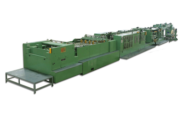
HT120-IIIASF Paper Tube Machine

Packaging principle of valve bag packaging machine

1. This type of packaging equipment mainly uses the motor as the most basic packaging power source to drive the impeller at the discharge seat to make it rotate smoothly, so as to achieve the purpose of evenly delivering the goods.

2. During the process of loading the goods into the weighing bag, the sensor contained in it will transmit the signal of the entire cargo volume to the microcomputer. When the weight reaches the weight signal that the microcomputer needs to output, the sealing cylinder of the package will The discharge port is sealed, and the filling process of a single packaging bag is completed at this moment.

3. After the sealed cylinder of the loaded material shrinks, and the packaging of the entire packaging bag is completed, the discharge nozzle will recover unobstructed.

For more detailed information about what kind of product packaging the valve bag packaging machine is mainly used for, click to visit:https://www.lyhuatianm.com/products-information/for-valve-bag-packaging-machine-product-packaging.html

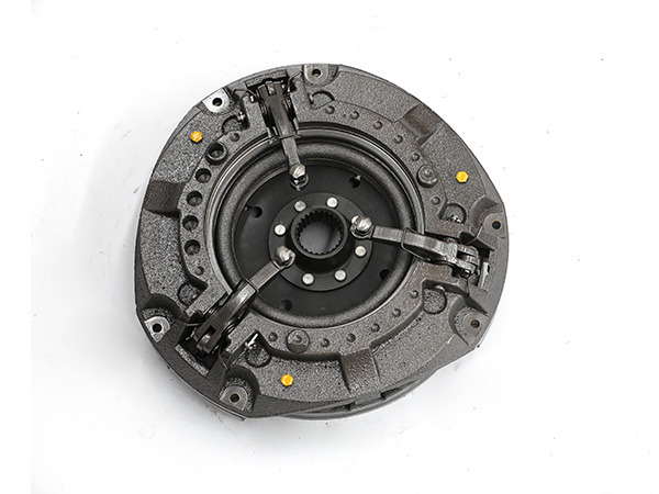
The clutch is a major assembly in the tractor drive train. When the tractor starts, the high-speed rotating engine is smoothly connected with the stationary drive train through the friction between the active part and the driven part of the clutch to ensure the vehicle starts smoothly. In the long-term use of tractor clutches, the wear and tear of parts is unavoidable, and the replacement of parts has become the main work of clutch repair. The quality of assembly and adjustment technology after parts replacement determines the service life of the clutch after repair. Next, we will mainly take a certain brand of 25 type tractor clutch as an example to introduce the assembly and adjustment points of single-plate dry clutch.

Tractor clutch assembly

1. Assembly of release bearing assembly

The clutch release bearing is installed between the clutch and the transmission, and the release bearing seat is installed on the tubular extension of the first shaft bearing cover of the transmission. The shoulder of the release bearing always touches the release fork through the return spring and retreats to the final position. Keep a clearance of 2.5 mm from the release lever. There should be an interference of 0.03 mm when the separation bearing seat is installed. During installation, the inner cavity of the bearing and bearing seat should be filled with butter, and there is no place for oiling the bearing at ordinary times.

2. Assembly of clutch pressure plate assembly

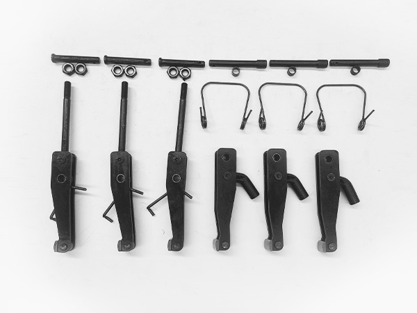
The assembly of the clutch pressure plate assembly is to assemble the pressure plate, spring, clutch cover and separation mechanism together, and the spring must be compressed before proceeding. The spring can be pressurized by means of mechanical pressurization or hydraulic pressurization by self-made simple support, and also can be pressurized on a radial drilling machine.

(1) Put the pressure plate on the platform, and place a circular backing plate with a thickness of 10 mm and an outer diameter slightly smaller than the diameter of the pressure plate under the pressure plate, or place three small nuts of the same thickness on it.

(2) Place the swing block, release lever, release lever adjustment screw and pin on the inner side of the boss of the pressure plate in sequence, put the spring on the boss of the cross-shaped spring seat, and align the clutch cover with the transmission plate in place Put it on the spring, make the 4 adjusting screws pass through the corresponding holes on the clutch cover, and straighten the transmission plate so that the unriveted end is aligned with the screw hole on the pressure plate.

(3) Pressurize the spring on the clutch cover, and compress the spring by more than 10 mm. At this time, screw on the adjusting nuts one by one, and then fix the transmission disc bolts together with the transmission disc bolt seats in the screw holes of the pressure plate, and punch riveting Bolt seat.

3. Installation of driven plate assembly and pressure plate assembly on the flywheel

This installation is mainly about the centering of the driven disc assembly, so during installation, the clutch shaft (namely the first shaft) can be used as the mandrel, or an optical shaft can be used instead. Insert the center of the driven disc with the optical shaft, insert it into the flywheel bearing hole, then install the pressure plate assembly to the plane of the flywheel, and tighten it diagonally with six M8×20 bolts. With the optical shaft pulled out, the center of the driven disc is correctly fixed on the flywheel.

More About Single Disc Dry Tractor Clutch Assembly and Adjustment:https://www.syclutch.com/news/assembly-and-adjustment-of-clutch-in-single-disc-dry-tractor.html

Three-dimensional cultivation is a three-dimensional model of soilless cultivation. This kind of cultivation is based on vertical gradient layered cultivation through vertical grow racks or in the form of erection and hanging without affecting flat cultivation, so as to improve land utilization. . All kinds of three-dimensional vertical grow racks are reasonably configured to maximize space utilization and ensure production while being more ornamental.

Spiral bionic column cultivation

The vertical grow racks are stacked in series in four directions in a spiral shape, forming a cultivation column, and the column is fixed, which is convenient for installation of the return pipeline. The spiral arrangement is conducive to the uniform lighting of each plant on the column. The matching two kinds of planting covers are conducive to the cultivation selection of a variety of flowers and leafy vegetables; it is conducive to the upright growth of each plant, and improves the commodity and product uniformity of leafy vegetables.

Bed square tube pipe hydroponics

Bed hydroponics consists of a cultivation system, a support and fixation system, a nutrient solution circulation system and a control system. The outer layer of the pipe wall is white and the inner layer is black. The unique double-layer structure prevents sunlight radiation and lowers the pipe temperature while creating an ecologically dark environment for better growth of plants. The dark environment eliminates the conditions for algae production to fundamentally solve the problem of algae associated with hydroponic vegetable production. Diversion grooves are designed on the upper and lower layers of the inner wall to allow the nutrient solution to flow fully and ensure the complete circulation of the nutrient solution.

Plant Grow Rack

Three-dimensional square tube pipe hydroponics

The three-dimensional pipe vertical grow racks is a deformed hydroponics method of bed pipe hydroponics. The horizontal pipes are passed through the brackets to make a space superimposed shape, which makes full use of the space and can form a good viewing effect.

Type A round pipe hydroponics

The A-type hydroponic pipeline is another deformed hydroponics method of the bed pipeline hydroponics. The horizontal pipeline is made into an A-shaped space superimposed through the bracket, which not only makes full use of the space, but also forms a good viewing effect.

For more detailed information about the three-dimensional cultivation mode, please click to visit:https://www.etegreen.com/blog/three-dimensional-cultivation-mode/

Speaking of crane slewing bearing wear, the inspection methods are mainly divided into rotary method and tilt method. As for which inspection method to choose, it is mainly determined whether to use the tilt method or the rotary method to measure the bearing wear according to the counterweight configuration of the crane.

The basic premise of the slewing method is that the bearing can always be tilted fully forward in the direction of the boom, and that this tilt follows the rotation of the crane.

1. There is no load on the hook, tighten the hook to a higher position, release the boom to the horizontal position (note that the boom does not collide with the platform facilities when turning horizontally) or lower the boom to the maximum limit position (the minimum level of the boom angle);

2. Use the base of the magnetic dial indicator to fix it to the position of the crane base, the magnetic pointer points to the clean and rust-free horizontal processing surface of the upper rotary disc, and adjust the pointer to the zero state (the reference 0 position point is established at this time);

crane slewing bearing

3. Slowly turn the crane 360 degrees, record the reading of the pointer every 45 degrees in the dynamic state, and confirm that the pointer reading should return to zero when the crane turns 360 degrees and returns to the initial position (record the elegant data when it does not return to the zero position value); for every four positions of the crane at intervals of 90 degrees, repeat the operation according to the above step 3, and record a total of 32 data in the four positions, and then organize them into a table for analysis.

The maximum permissible deviation is required to be 1.7mm, and the measurement accuracy of the dial indicator measuring instrument is at least +0.05mm or more.

The premise of the tilt method is that the bearing can be fully tilted forward and backward by using the counterweight, boom luffing or jack. The purpose is to measure the total clearance between the inner raceway of the bearing and the rolling elements without causing obvious moment of elastic deformation on the bearing.

For more detailed information on inspection methods for crane slewing bearing wear, click to visit:https://www.excavatorbearing.com/a/bearing-knowledge/inspection-method-for-wear-of-slewing-bearings-of-cranes.html

Multi-directional die forging is a precision forging technology that performs split-die forging on a multi-directional die forging hydraulic press, and its deformation is mainly extrusion. During multi-directional die forging, two or more punches (or punch cores) pressurize the bad material simultaneously or sequentially from different directions for extrusion or upsetting.

Compared with ordinary die forging and split die forging, multi-directional die forging has the characteristics of simple structure and long service life. Forgings such as class, cylindrical parts, large valve bodies, pipe joints, aircraft landing gear, engine casings, disc shaft assemblies, etc. have begun to be produced by multi-directional die forging technology. Combined with the application of multi-directional die forging, we have made a detailed summary of the process characteristics of multi-directional die forging, let’s understand it together.

Other agricultural machinery forgings

MULTI-DIRECTIONAL DIE FORGING PROCESS CHARACTERISTICS

1. The material utilization rate is high. Compared with the open die forging, there is no waste of flash material. The shape of the forging can be designed to be hollow, and the forging slope of the punching hole can be canceled or reduced, thereby saving 30%-50% of metal.

2. The performance of the forging is good. Since the shape of most forgings is formed by die forging, the fiber structure is distributed along the contour of the forging, so the mechanical properties of the forging are good, and the general strength can be increased by more than 30%.

3. It is suitable for the forming of high alloy steel and special alloy. Because the blank is deformed under three-dimensional compressive stress during forging, its process plasticity is improved, which greatly facilitates the forming of high alloy and special alloy materials with poor plasticity and narrow forging temperature range.

For more detailed information about the characteristics of the multi-directional die forging process, please click to visit:https://www.gold-emperor.com/multi-directional-die-forging-process-characteristics/

Robot bearings are generally used as joint bearings. The commonly used robot bearings are cross roller bearings and thin-walled bearings with equal cross-section. These two bearings are one of the key accessories for robots. When selecting robot bearings It must be selected according to actual needs, and there are also many precautions when choosing.

The selection method of robot bearings

robot bearings

1. Selection of bearing type

The bearing model is generally selected by the user’s technicians according to the use conditions of the supporting products and the bearing load. The business personnel mainly understand whether the actual load of the user is in line with the requirements. If the load cannot meet the usage requirements, they should advise the customer to change the model as soon as possible, but unless it is a special product, generally there will be no problem in the selection of the model.

2. Selection of bearing clearance

When purchasing uranium bearings, users generally only inform them of the type and grade, and rarely ask for the clearance of the bearing. They need to understand the service conditions of the bearing, and the bearing speed, temperature, and fit tolerance are directly related to the bearing clearance.

3. Oil selection

The choice of grease is generally based on the special speed of the shaft, temperature resistance, noise requirements and starting torque.

More detailed information about robot bearing selection methods can be accessed by clicking:https://www.prsbearings.com/a/news/robot-bearing-selection-method.html

One of the commonly used processing equipment in the field of calcium powder processing is hydrated lime equipment. With the strong requirements of the environmental protection department for the powder processing industry to strictly prohibit dust pollution. From a single piece of equipment, it has developed into an entire calcium hydroxide production line that is basically automated from automatic lime feeding to automatic ash, automatic slag discharge, automatic dust collection, automatic powder selection, and automatic quantitative weighing and packaging.

The entire line It is environmentally friendly and labor-saving, which greatly reduces the operating cost of calcium powder processing. With the continuous development of science and technology, if we want to gain a firm foothold in the fierce market competition, we must increase the investment in science and technology. How to realize the automation of equipment has become a problem that manufacturers are very concerned about.

Assembly line industrial production will have more advantages in automated production. In fact, for the production of basic hydrated lime, if a relatively basic assembly line operation method can be achieved, the output of hydrated lime will also be improved. For the basic hydrated lime production line It is also necessary to realize basic automation. Of course, this needs to ensure the perfection of some core parts of the production equipment.

The use of hydrated lime equipment is also based on a relatively complete system for basic operations. For the production of basic calcium hydroxide, the current production equipment can already guarantee the output and quality. If the production of the equipment is more If it is perfect, there is basically no need for human operation. Of course, this requires the hydrated lime production line to have a complete drive system, transmission system, execution system, detection system, and control system. Five major systems.

1. Drive system. The driving system is the power source of the main machine, only with the driving system can the hydrated lime production line run.

2. Transmission system. Through the transmission device, the kinetic energy can be transmitted to each execution system, so that the execution system has kinetic energy, so that the purpose of transportation can be achieved, and the energy can also be transferred to the auxiliary system in the hydrated lime production line.

For more detailed information about the automatic production of calcium hydroxide equipment, please click to visit:https://www.ly-gaifeng.com/blog/automatic-production-of-hydrated-lime-production-line.html

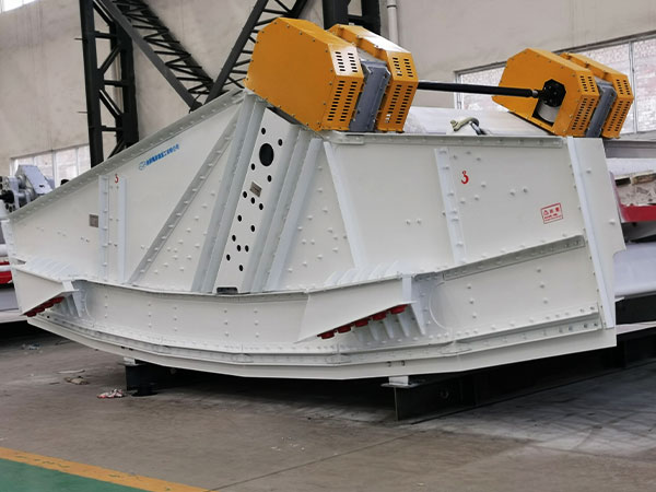
Linear vibrating screen is a multifunctional screening and grading machine. It is widely used in mining, coal, smelting, motor installation process, building materials, refractory materials, light industry, chemical industry and other industries. It has the advantages of large output and high precision. About linear vibrating screen how much do you know about the installation?

What should be paid attention to when installing the linear vibrating screen?

Install the vibrating motor of the linear vibrating screen, the connecting screws must be tightened before use, especially three days before the trial of the new screen machine, it must be tightened repeatedly to avoid loosening and causing accidents; vibration damping spring: prevent vibration from being transmitted to the ground, and at the same time support the screen box The full weight, when installed, the spring must be perpendicular to the ground; screen frame: made of pine or wood with less deformation, mainly used to keep the screen flat and achieve normal screening;

Screen: There are several kinds of screens such as low carbon steel, brass, bronze, stainless steel wire, etc.; Bracket: It is composed of four pillars and two channel steels, supporting the screen box. When installing, the pillars must be vertical to the ground. The channel steel should be parallel to each other; screen box: it is welded by several steel plates with different thicknesses, has certain strength and rigidity, and is the main component of the screen machine.

The linear vibrating screen motor should have reliable grounding. There is a grounding device inside the motor, and the lead end has a mark. It can also be grounded with strong bolts on the foot; the motor should be fastened on the installation surface, and the installation surface must be smooth and flat; the motor can be installed horizontally. ;Adjustment of excitation force; The motor lead wire adopts four-core rubber cable, and the lead wire cable is not allowed to have sharp bends when connected to the power supply, and it is reliably fixed with the vibrating body.

Installation steps and methods of linear vibrating screen

Linear vibrating screen

1. The linear vibrating screen should be checked before installation

(1) Whether the packaging is complete and undamaged, and whether it is damp;

(2) Whether the motor is deformed or damaged during transportation, whether the parts are complete, and whether the fasteners are loose or falling off;

(3) Whether the motor nameplate data meet the requirements;

For more detailed information about the installation precautions of the linear vibrating screen, please click to visit:https://www.hsd-industry.com/news/precautions-for-installing-linear-vibrating-screen/

The quality of the roller skin of the briquetting machine directly determines the service life of the briquetting machine. The hardness of the roller skin is the most important parameter to measure the quality of the roller skin of the briquetting machine. The hardness of the roller skin depends on the alloy steel grade selected for the roller skin and the final level of heat treatment process.

The production process of the roller skin of the ball press

Firstly, the blank is made according to the drawing of the roll skin, and then processed by turning, so that all sides are clean and eight sides are smooth. The next step is to carve the ball socket on the circumference of the roller skin. Of course, the size and shape of the ball socket need to be determined according to the diameter of the roller skin and the pressed material and other factors. The latter process is heat treatment, which is also the most critical process. In the case of the same raw material of the roll skin, the hardness of the roll skin is determined by the heat treatment.

Ball press roller skins can be divided into two types in terms of technology: casting and forging. The commonly used steel grade for casting roll skin is 65 manganese alloy, the cost is relatively low, but the hardness of the roll skin is not too high, not very wear-resistant, suitable for pressing fine materials such as coal powder and clay. The commonly used steel grade for forging roller skins is 92 chromium molybdenum, which is relatively high in price and cost, but the hardness of the made roller skins is also relatively high, which can reach above HRC62, and is suitable for pressing rough materials such as iron powder and metal ore powder.

roller-shell

1. The material of the roller skin of the briquetting machine

The material of the roller skin of the briquetting machine is divided into 65 manganese, 9 chromium and 2 molybdenum, high chromium alloy and so on. When pressing different materials, different roller skins should be selected: 65 manganese roller skins are more popular and belong to steel castings with low cost. , can suppress coal powder, coke powder, charcoal powder and other materials; 9 chromium 2 molybdenum, high chromium alloy briquette machine pressure rollers are forged parts, mainly used in medium and large briquette briquetting machines with high output, and can be used to suppress ore powder, iron concentrate powder, magnesium oxide powder, laterite nickel ore, etc.

For more detailed information about the production process of ball press roller skin, please click to visit:https://www.zymining.com/blog/ball-press-roller-skin-production-process.html

The tank body of the water tank truck is generally made of high-quality carbon steel plate, and the thickness of the plate is generally between 4-6mm. In order to improve the corrosion resistance and service life of the steel tank body, corrosion-resistant materials or stickers can be sprayed on the inner surface of the tank Anti-corrosion lining is applied, and some measures are taken for anti-corrosion treatment.

Generally, the common methods for anti-corrosion treatment of water tank trucks are:

water tank truck

(1) Zinc coating: used for shipping gasoline, benzene, mixed xylene, cement, water, excrement and other materials.

(2) Painting: Due to the filling of water, cement, excrement and other materials

(3) Tin coating: used for shipping light oil, heavy oil, lubricating oil and other petroleum products.

(4) Lead-coated: Pure lead is a very good corrosion-resistant material. Lead-coated tanks are suitable for shipping dilute sulfuric acid and benzyl chloride, but not for hydrochloric acid and alkalis. Lead and its alloys are poisonous and should not be in contact with food items. They are also harmful to the human body, and protective measures should be taken when using them.

For more detailed information about the anti-corrosion method of water tankers, please click to visit:https://www.ly-cimc-linyu.com/a/news/water-tanker-anti-corrosion-treatment-method.html