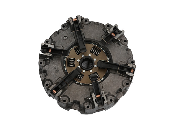
Tractor friction discs, commonly referred to as clutch discs, come in a variety of sizes depending on the make and model of the tractor, as well as the specific application and design of the clutch system. The size of a friction disc is typically determined by its outer diameter, inner diameter, and thickness. These measurements can vary significantly between different tractor manufacturers and models.

To provide a general idea, I can give you a range of possible dimensions for tractor friction discs. Keep in mind that these measurements are approximate and may not cover all possible variations:

Outer Diameter: 6 inches (150 mm) to 14 inches (355 mm) or more.

Inner Diameter (center hole): 1 inch (25 mm) to 2.5 inches (64 mm) or more.

Thickness: 0.25 inches (6 mm) to 1 inch (25 mm) or more.

For more detailed information about the size of the tractor friction disc, which parts constitute the detailed information, please click to visit: https://www.syclutch.com/news/tractor-friction-disc-sizes.html

A tractor clutch assembly is a critical component of the tractor’s drivetrain system, allowing the driver to engage and disengage power from the engine to the transmission. It’s a complex system consisting of several components that work together to facilitate smooth and controlled power transfer. The specific components included in a tractor clutch assembly can vary depending on the tractor’s design and transmission type, but here are the main components commonly found in a tractor clutch assembly:

Clutch Disc: The clutch disc, also known as the friction disc or clutch plate, is a circular component that’s located between the flywheel and the pressure plate. It has friction material on both sides that engages with the pressure plate and the flywheel. When the clutch is engaged, the clutch disc is pressed against the flywheel to transfer power from the engine to the transmission.

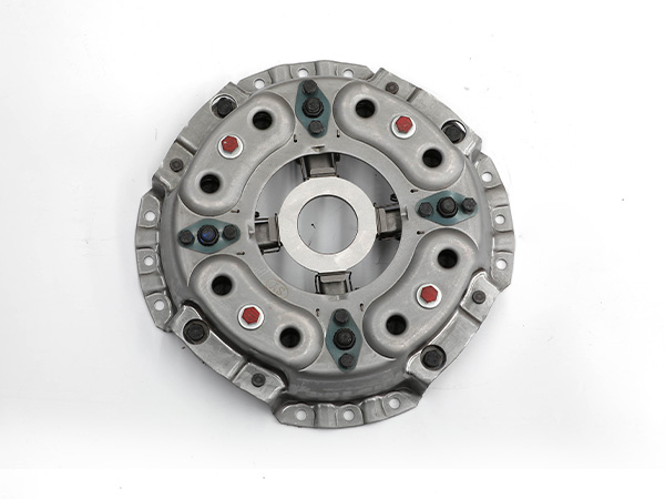
Pressure Plate: The pressure plate is a circular plate that applies pressure to the clutch disc when the clutch pedal is released. This pressure ensures that the clutch disc is firmly engaged with the flywheel, allowing power transfer.

13-inch

Flywheel: The flywheel is a heavy, circular disc mounted on the engine’s crankshaft. It provides inertia and helps smooth out engine power delivery. The clutch disc engages with the flywheel, allowing power transfer from the engine to the transmission.

Clutch Release Bearing (Throw-out Bearing): The release bearing is a bearing that applies pressure to the diaphragm spring of the pressure plate. When the clutch pedal is depressed, the release bearing disengages the clutch by releasing pressure from the pressure plate.

Clutch Fork: The clutch fork is a lever that’s actuated by the clutch pedal through a mechanical linkage or hydraulic system. When the clutch pedal is depressed, the clutch fork moves the release bearing against the pressure plate’s diaphragm spring, disengaging the clutch.

Pilot Bearing/Bushing: This bearing or bushing supports the transmission input shaft and allows it to rotate smoothly when the clutch is engaged. It’s usually located in the center of the flywheel.

Clutch Housing/Cover: The clutch housing or cover encloses the clutch assembly and provides protection. It’s typically attached to the engine and also serves as a mounting point for the pressure plate and release bearing.

For more detailed information about the components of the tractor clutch assembly, please click to visit: https://www.syclutch.com/news/tractor-clutch-assembly-composition.html

A tractor clutch assembly is a crucial component in the powertrain system of a tractor or other agricultural machinery. It’s responsible for engaging and disengaging the power transmission between the engine and the rest of the drivetrain, allowing the operator to control the movement of the tractor.

How a tractor clutch assembly works

13-Inch

Clutch Disc: The clutch disc, also known as the friction disc, is a circular plate lined with friction material on both sides. It is located between the engine’s flywheel and the transmission input shaft. When engaged, the clutch disc is pressed against the flywheel by the pressure plate, transmitting engine power to the transmission.

Pressure Plate: The pressure plate is a heavy-duty spring-loaded component that applies pressure to the clutch disc. When the clutch pedal is released, the pressure plate clamps the clutch disc against the flywheel, allowing power to be transmitted from the engine to the transmission.

Flywheel: The flywheel is a heavy rotating disc connected to the engine’s crankshaft. It provides inertia and helps smooth out the engine’s power delivery. The clutch disc is mounted to the flywheel, and the pressure plate engages with it.

14-Inch-29-Spline-Copper-Based

Release Bearing (Throwout Bearing): The release bearing is a component that engages with the fingers or levers of the pressure plate. When the clutch pedal is depressed, the release bearing moves the pressure plate away from the clutch disc, disengaging the clutch and interrupting the power transmission.

Clutch Fork: The clutch fork is a lever that is actuated by the clutch pedal through the clutch linkage. When the clutch pedal is depressed, the clutch fork pushes or pulls the release bearing, which in turn releases the pressure on the clutch disc.

For more detailed information on the working principle of the tractor clutch assembly, please click to visit: https://www.syclutch.com/news/working-principle-of-tractor-clutch-assembly.html

A tractor clutch kit is a set of components and parts designed to replace or repair the clutch system in a tractor. The clutch is a critical component in the powertrain of a tractor, as it allows the operator to engage or disengage the power from the engine to the transmission. This enables the tractor to start smoothly, shift gears, and stop without stalling the engine.

Choosing the right tractor clutch kit is essential to ensure the efficient operation and longevity of your tractor’s clutch system. Here are some factors to consider when selecting a tractor clutch kit:

Tractor Model and Compatibility

Ensure that the clutch kit you choose is compatible with the make and model of your tractor. Different tractor models may have variations in their clutch systems, so it’s crucial to get a kit that fits your specific tractor.

Quality of Components

Look for a clutch kit that includes high-quality components, such as the pressure plate, clutch disc, release bearing, and pilot bearing. Quality components will ensure better performance, durability, and reduced risk of premature wear and failure.

12 Inch 26 Spline

Application and Intended Use

Consider the intended use of your tractor when choosing a clutch kit. Tractors used for heavy-duty tasks, such as plowing or towing, may require a clutch kit designed to handle higher loads and provide better torque transfer.

OEM vs. Aftermarket

You can choose between Original Equipment Manufacturer (OEM) clutch kits or aftermarket options. OEM kits are manufactured by the tractor’s original manufacturer and are specifically designed for your tractor model. Aftermarket kits are produced by third-party manufacturers and may offer a more affordable alternative while still maintaining good quality. Make sure to choose a reputable aftermarket brand.

Performance

If you require enhanced performance from your tractor, such as increased torque capacity or smoother engagement, consider clutch kits with performance upgrades. Some kits may have better friction materials or improved designs to cater to specific performance needs.

For more detailed information on how to choose a tractor clutch kit, click to visit: https://www.syclutch.com/news/tractor-clutch-kit-choose.html

Choosing a valve bag making machine involves considering various factors to ensure that the machine meets your production needs, quality requirements, and budget. Valve bags are commonly used for packaging bulk materials like cement, chemicals, minerals, and agricultural products.

The key factors to consider when selecting a valve bag making machine

  • Bag Size and Style: Determine the range of bag sizes and styles (e.g., dimensions, valve types) that you need the machine to produce. Some machines are designed for specific bag sizes, while others offer flexibility to accommodate a range of sizes.
  • Production Capacity: Assess your production requirements in terms of bags per minute or bags per hour. Choose a machine that can handle your desired production rate while maintaining consistent quality.

HD200D-IIIDJ Square Bottom Machine

  • Material Compatibility: Consider the types of materials you plan to use for the bags. Different bag making machines are optimized for specific materials, such as paper, woven polypropylene, or other plastics. Ensure that the machine is compatible with your chosen bag material.
  • Bag Quality: The quality of the bags produced is crucial. Look for a machine that can consistently produce bags with accurate dimensions, strong seals, and proper valve attachment. Quality control features like tension control and alignment systems can contribute to better bag quality.
  • Automation and Features: Evaluate the level of automation the machine offers. Some machines come with advanced features like automatic tension control, servo-driven systems, and touchscreen interfaces for easy operation and precise control.

For more detailed information on how to choose a valve bag making machine, please click to visit: https://www.lyhuatianm.com/products-information/valve-bag-making-machine-selection.html

Paper tube packaging, also known as cardboard tube packaging or paper can packaging, refers to a type of packaging made from cylindrical tubes constructed using paper or cardboard materials. These tubes are commonly used to package a variety of products, providing a durable and eco-friendly solution for both protection and presentation.

Here are some key features and uses of paper tube packaging:

Construction: Paper tube packaging is typically made by rolling and gluing layers of paper or cardboard into a cylindrical shape. The ends of the tube can be closed with various types of caps, plugs, or lids, depending on the specific application.

Materials: The tubes are usually made from sturdy and sustainable materials such as Kraft paper, recycled paperboard, or other types of cardboard. The choice of material can vary based on the desired strength, appearance, and environmental considerations.

HD100-IB Square Bottom Machine

Applications: Paper tube packaging is versatile and can be used to package a wide range of products, including but not limited to:

  • Food items like snacks, spices, tea, coffee, and confectionery.
  • Cosmetics and personal care products like creams, lotions, and lip balms.
  • Small items such as promotional materials, promotional pens, USB drives, etc.
  • Retail packaging for specialty products.
  • Gift packaging for items like candles, small electronics, and accessories.
  • Rolled documents, posters, and artwork.
  • Industrial components, such as certain types of textiles, fabrics, and materials.

For more detailed information about what is paper tube packaging, click to visit: https://www.lyhuatianm.com/products-information/what-is-paper-tube-packaging.html

A valve bag making machine is a type of equipment used in industrial packaging to produce valve bags. Valve bags are a specific type of packaging often used for powdery or granular materials, such as cement, flour, chemicals, fertilizers, and more. These bags are designed with a valve or spout that can be opened for filling and then closed to seal the contents. Valve bags offer convenience, cleanliness, and efficient filling, making them popular for various industries.

The cost of a valve bag making machine can vary widely depending on several factors, including the brand, model, features, production capacity, and additional customization options.

HD100-IB Square Bottom Machine

Basic valve bag making machines might start at a few thousand dollars, while more advanced and high-capacity models can range from tens of thousands to several hundred thousand dollars or more. The complexity of the machine, the quality of materials used, and the automation features will all contribute to the overall cost.

Keep in mind that purchasing a valve bag making machine is an investment, and it’s important to consider not only the upfront cost but also factors like maintenance, operational costs, training, and potential technical support.

Valve bag making machines play a crucial role in the efficient and automated production of valve bags, which are widely used in industries that require hygienic and controlled packaging for bulk materials.

The valve bag making machine typically consists of several components and stages:

HD100-ID-3

Material Handling and Unwinding: The machine starts by unwinding a roll of the packaging material (usually paper or plastic) that will be used to create the valve bags. The material is guided through the machine for further processing.

Printing (Optional): If required, the machine can include a printing section where information, branding, or labels can be printed onto the packaging material.

Cutting: The machine cuts the continuous sheet of material into individual bag blanks of the desired size. The cutting process may involve rotary knives, guillotine cutters, or other mechanisms, depending on the design of the machine.

For more detailed information about how much the valve bag making machine, please click to visit: https://www.lyhuatianm.com/products-information/valve-bag-making-machine-price.html

A square bottom paper bag machine is a type of industrial machinery used to manufacture square or block bottom paper bags. These bags have a flat bottom and stand upright, making them ideal for packaging various products such as food items, groceries, cement, chemicals, and more. Square bottom paper bags are popular for their sturdiness, making them suitable for carrying heavy or bulky items.

The working principle of a square bottom paper bag machine involves several steps to produce the bags efficiently:

HD100-IB Square Bottom Machine

Paper Roll Unwinding: The machine begins by unwinding a large roll of paper. The paper used is typically kraft paper or other types suitable for bag-making applications.

Printing (Optional): Some machines are equipped with printing units to add logos, designs, or information to the paper before it is converted into bags.

Paper Feeding: The paper is fed into the machine through a series of rollers and guides, ensuring proper alignment and tension.

Bottom Folding: The machine folds the bottom of the paper to create the square or block bottom shape. The folding process involves multiple steps, and adhesive or glue is often applied to secure the bottom fold.

Side Sealing: The machine seals the sides of the bag to form a tubular shape.

Bag Cutting: The tubular shape is then cut into individual bags of the desired length.

Square Bottom Formation: The bottom folds are further secured to create a stable square or block-shaped base for the bag.

Bag Delivery: The finished square bottom paper bags are counted and stacked for collection or further processing.

For more detailed information about the working principle of the square bottom paper bag machine, please click to visit: https://www.lyhuatianm.com/products-information/working-principle-of-square-bottom-paper-bag-machine.html

A vibrating screen, also known as a sieve or a separator, is a mechanical device used to separate materials by particle size through the vibration and movement of the screen surface. The effectiveness of a vibrating screen depends on several factors, including the type of material being processed, the amplitude and frequency of the vibrations, the angle of inclination of the screen, and the design of the screen itself.

How the effectiveness of a vibrating screen

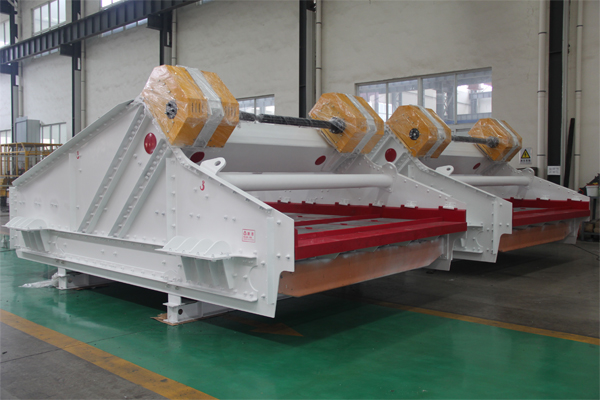
Double banana sieve

Particle Separation

The primary purpose of a vibrating screen is to separate particles based on their size. The screen’s mesh or opening size determines the size of particles that can pass through. Larger particles are retained on the screen surface and are referred to as oversize, while smaller particles pass through and are referred to as undersize. The effectiveness of the screen is determined by how accurately it separates these particles according to size.

Screening Efficiency

The screening efficiency of a vibrating screen refers to the percentage of undersize particles in the feed material that actually pass through the screen and are collected as product. Higher screening efficiency indicates that the screen is effectively separating particles of the desired size. Factors such as vibration amplitude, frequency, and screen inclination play a role in determining screening efficiency.

Capacity

The capacity of a vibrating screen is the amount of material it can process in a given time period. An effective vibrating screen should be able to handle the desired capacity without causing excessive wear, blinding of the screen surface, or other operational issues.

Screen Blinding

Screen blinding occurs when particles become trapped in the openings of the screen, reducing the effective open area and diminishing the screening efficiency. This can happen due to factors like moisture, fine particles, and high feed rates. Effective screen designs incorporate features to minimize blinding, such as anti-blinding devices and screen surface treatments.

For more detailed information about the effect of the vibrating screen, click to visit: https://www.hsd-industry.com/news/how-effective-is-a-vibrating-screen/

The working principle of a horizontal screen, also known as a horizontal vibrating screen, revolves around the concept of mechanical vibration and motion to separate, classify, and convey materials. Horizontal screens are commonly used in industries such as mining, construction, aggregate processing, and more for tasks like sizing, dewatering, and scalping of various materials.

The working principle of a horizontal screen:

High Frequency Dehydration Vibrating Screen

1. Structure: A horizontal screen consists of a rectangular or slightly inclined box-like structure called a “deck.” The deck is mounted on a frame and is typically equipped with multiple screen layers or decks stacked on top of each other.

2. Vibration Mechanism: Horizontal screens use a vibration mechanism to generate the necessary motion for material separation. This mechanism is usually provided by one or more vibrators mounted on the sides of the screen. These vibrators generate oscillating or circular vibrations that cause the screen deck and the material on it to vibrate.

3. Material Loading: The material to be screened is fed onto the screen deck from the top or one end. The material spreads across the width of the deck, forming a thin layer.

4. Separation: As the screen deck vibrates, the material experiences a combination of vertical and horizontal motions. The vertical component lifts the material, allowing smaller particles to pass through the gaps in the screen mesh or openings. The horizontal motion propels the material forward along the deck.

Linear Vibrating Screen

5. Sizing and Classification: Depending on the size of the openings in the screen mesh, particles that are smaller than the openings will fall through and be collected as undersize material, while particles larger than the openings will remain on the screen and be collected as oversize material. This process classifies the material into different size fractions.

6. Decks and Multiple Layers: Horizontal screens often have multiple decks or layers of screens stacked on top of each other. Each deck may have different screen mesh sizes to further refine the material into different size categories.

For more detailed information about the working principle of the horizontal screen, click to visit: https://www.hsd-industry.com/news/horizontal-screen-working-principle/