Angular contact ball bearings are a type of precision rolling-element bearing designed to accommodate both radial and axial loads. They are commonly used in various industries and applications where precise rotational movement and high load-carrying capacity are required.

The application fields of angular contact ball bearings

Machine Tools

Angular contact ball bearings are widely used in machine tool applications, such as lathes, milling machines, and grinding machines. They provide high precision and stiffness to ensure accurate machining operations.

Aerospace

Aircraft, helicopters, and spacecraft often use angular contact ball bearings in critical components like landing gear, control surfaces, and jet engine assemblies. They can handle high-speed and high-temperature conditions.

Angular contact ball bearings

Automotive

In automotive applications, angular contact ball bearings can be found in wheel hubs, drive shafts, and transmissions. They help support both radial and axial loads while allowing for precise steering and smooth operation.

Wind Turbines

Angular contact ball bearings are used in wind turbine gearboxes to withstand the heavy loads and variable operating conditions associated with wind energy generation.

Industrial Gearboxes

Gearboxes in various industrial machinery, including conveyor systems, pumps, and heavy equipment, often rely on angular contact ball bearings to transmit power efficiently.

Robotics

Angular contact ball bearings are used in robotic joints and arms, where they enable precise movement and positioning of robotic components.

Medical Equipment

High-precision medical devices such as surgical instruments, CT scanners, and X-ray machines may use angular contact ball bearings for smooth and accurate motion.

For more detailed information about the application fields of angular contact ball bearings, please click here: https://www.boyingbearing.com/en/a/news/angular-contact-ball-bearing-applications.html

A rotary table bearing, also known as a slewing bearing or turntable bearing, is a specialized type of rolling-element bearing designed to support axial, radial, and moment loads simultaneously while facilitating rotational movement. These bearings are commonly used in various applications that require smooth and controlled rotation, such as in cranes, excavators, wind turbines, and other heavy machinery. Rotary table bearings play a crucial role in enabling these machines to pivot, swivel, or rotate.

Features of rotary table bearings

rotary table bearing

Design

Rotary table bearings have a unique design that allows them to support heavy loads while enabling 360-degree rotational movement around a central axis. They consist of an inner ring (sometimes called the “race”), an outer ring, rolling elements (such as balls or rollers), and sometimes a cage or separator.

Axial and Radial Load Capacity

These bearings are designed to handle both axial (thrust) and radial (horizontal) loads simultaneously. This ability to support combined loads is one of their defining features. They can also accommodate moment loads, which are rotational forces applied perpendicular to the bearing’s axis.

Low Profile

Rotary table bearings are often characterized by their relatively low profile or slim design. This allows them to fit into compact spaces while providing high load capacity.

Precision and Smooth Rotation

They are manufactured with high precision to ensure smooth and precise rotation. This is especially important in applications like machine tools, robotics, and radar systems where accurate positioning is critical.

Gear Options

Some rotary table bearings come with integrated gears (such as external or internal gears) that allow for controlled rotation. These gears can be used in conjunction with motors or other drive systems to achieve precise positioning and motion control.

For more detailed information about the features of rotary table bearings, please click here: https://www.boyingbearing.com/en/a/news/rotary-table-bearings-features.html

Adjusting the clutch on a tractor is an essential maintenance task to ensure proper engagement and disengagement of the clutch mechanism. A well-adjusted clutch can improve the overall performance and longevity of the tractor. Here are the general steps to adjust a tractor clutch:

Safety Precautions:

Before adjusting the clutch on a tractor, ensure the tractor is safely parked, the engine is off, and the ignition key is removed. Follow all safety guidelines and use appropriate personal protective equipment.

Tools and Materials:

You may need the following tools and materials:

  • Wrenches (usually open-end or socket wrenches)
  • Screwdrivers
  • Clutch adjustment manual (specific to your tractor model)
  • Jack and jack stands (if necessary)

Procedure:

13-Inch-10-Spline-PTO-Disc-Asbestos-free

1. Consult the Manual: Always refer to the tractor’s user manual or service manual for specific instructions on adjusting the clutch. Different tractor models may have unique procedures and requirements.

2. Locate the Clutch: Find the clutch adjustment mechanism on your tractor. It is typically located in the area where the clutch pedal connects to the clutch linkage or clutch housing.

3. Adjust the Clutch Pedal Free Play:

  • Measure the clutch pedal free play. This is the distance the pedal moves before resistance is felt.
  • If there is too much free play, you will need to reduce it. If there is too little, you will need to increase it.
  • Loosen the locknut on the clutch pedal linkage.
  • Adjust the linkage to achieve the desired free play, as specified in the manual.
  • Tighten the locknut to secure the adjustment.

4. Check the Clutch Release Mechanism:

  • Inspect the clutch release mechanism for any signs of wear, damage, or misalignment. This may include the clutch release bearing and the fork.
  • Replace any worn or damaged parts as necessary.

For more detailed information about the tractor clutch adjustment method, please click here: https://www.syclutch.com/news/tractor-clutch-adjustment-method.html

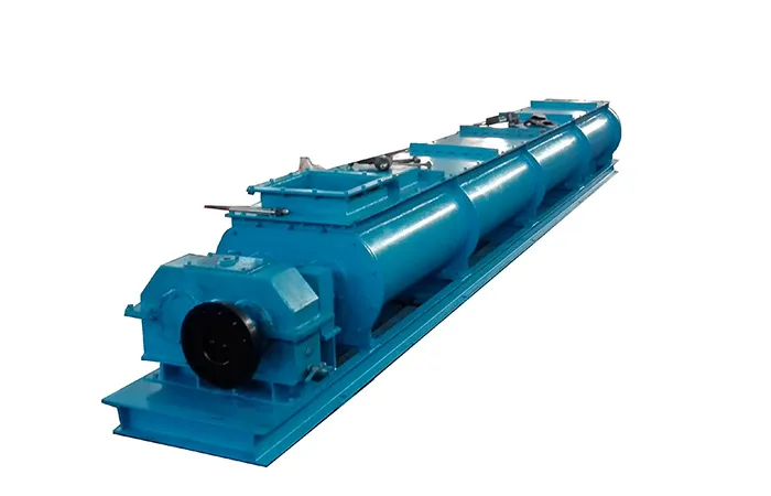
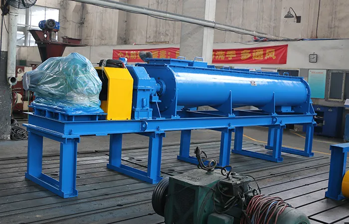
A sludge briquetting machine, also known as a sludge briquette press, is used to convert sludge into briquettes. Sludge is a semi-solid or solid waste material produced during various industrial processes, wastewater treatment, or sewage treatment. The purpose of a sludge briquetting machine is to compress and solidify the sludge into a more manageable and transportable form.

The working principle of a sludge briquetting machine

Preparation of Sludge

The first step is to collect and prepare the sludge. This may involve dewatering the sludge to reduce its moisture content and separate it from excess water. Lower moisture content makes the sludge more suitable for briquetting.

Feeding

The prepared sludge is fed into the hopper of the briquetting machine. Some machines may also have a mixer to homogenize the sludge and ensure an even consistency.

Compression

Inside the briquetting machine, there is a chamber or cylinder where the sludge is compressed. The working principle typically involves the use of a hydraulic or mechanical press. Here’s how it works:

1) Hydraulic Press

In a hydraulic sludge briquetting machine, a hydraulic system is used to exert a tremendous amount of pressure on the sludge. A piston or plunger is driven into the cylinder, compressing the sludge.

2) Mechanical Press

In a mechanical sludge briquetting machine, a mechanical lever or screw mechanism is used to apply pressure to the sludge. As the lever is activated or the screw is turned, it forces the sludge into a compact form.

Briquette Formation

As the sludge is compressed under high pressure, it undergoes a transformation into briquettes. The pressure causes the sludge particles to bind together, forming solid, compacted briquettes.

For more detailed information on the working principle of the sludge briquetting machine, please click to visit: https://www.zymining.com/en/a/news/working-principle-of-sludge-briquetting-machine.html

Cylindrical roller bearings are a type of rolling-element bearing designed to handle radial loads (loads that act perpendicular to the axis of rotation). They consist of cylindrical rolling elements placed between inner and outer rings. These bearings are widely used in various applications where rotational motion is involved and where high radial load capacity, precision, and rigidity are essential.

Common uses of cylindrical roller bearings

cylindrical roller bearings

Machinery and Industrial Equipment

Cylindrical roller bearings are commonly used in a wide range of industrial machinery and equipment, including machine tools, textile machinery, printing presses, papermaking machines, and conveyor systems. They provide support for rotating components like shafts and spindles.

Automotive Applications

In the automotive industry, cylindrical roller bearings can be found in various parts of a vehicle, including engine components, transmissions, axles, and wheel hubs. They help support and guide rotating parts while withstanding the forces encountered during vehicle operation.

Railway and Transportation

Cylindrical roller bearings are used in locomotives, freight cars, passenger trains, and light rail systems to handle the loads and vibrations associated with rail transportation.

Aerospace and Aviation

They are employed in aircraft engines, landing gear assemblies, and various aircraft subsystems to handle high radial loads and maintain precision in critical components.

Construction and Heavy Machinery

Cylindrical roller bearings are used in construction equipment, such as cranes, excavators, and bulldozers, where they support the heavy loads and ensure smooth movement of machinery components.

For more detailed information about the uses of cylindrical roller bearings, please click to visit: https://www.boyingbearing.com/en/a/news/crossed-cylindrical-roller-bearing-used.html

A 4-post rack, also known as an open frame rack, is a type of equipment rack used for mounting servers, networking equipment, and other rack-mounted devices. The dimensions of a standard 4-post rack can vary depending on the specific manufacturer and model, but here are some common dimensions you might encounter:

Height

4-post racks come in various heights, typically measured in rack units (U) or rack spaces. Common heights include 12U, 24U, 42U, and 45U. One rack unit (1U) is equivalent to 1.75 inches (44.45 millimeters) of vertical space.

4-post rack

Width

The standard width for a 4-post rack is 19 inches (482.6 millimeters). This width is standardized for mounting network and server equipment.

Depth

The depth of a 4-post rack can vary significantly, depending on the specific application and the equipment it’s intended to hold. Common depths range from 24 inches (609.6 millimeters) to 36 inches (914.4 millimeters) or more.

Overall Dimensions

The overall dimensions of the rack will depend on its height, width, and depth. For example, a common size might be 42U in height, 19 inches in width, and 36 inches in depth.

Weight Capacity

The weight capacity of a 4-post rack can also vary. It’s important to check the manufacturer’s specifications to ensure that the rack can support the weight of the equipment you plan to mount.

For more detailed information on the dimensions of 4-post racks, please click here: https://www.etegreen.com/en/a/news/4-post-rack-dimensions.html

Steel office furniture is valued for its durability and ability to withstand heavy daily use. It is often chosen for its modern and industrial appearance, and can be found in a variety of styles to suit different office aesthetics. Additionally, steel furniture is relatively easy to clean and maintain, making it a practical choice for busy office environments. The price of steel office furniture is also affected by many factors. Regarding the influencing factors, steel office furniture manufacturers gave us a detailed introduction.

Factors affecting the price of steel office furniture

Steel office furniture

Material Quality

The quality of the steel used in furniture is an important determinant of its price. High-quality steel is more durable and resistant to corrosion, and tends to be more expensive.

Design and Style

Elaborate or custom-designed steel office furniture is often more expensive than standard simple designs. Unique, fashionable styles can also fetch higher prices.

Brand

Well-known brands often charge a premium for their products because of their reputation for quality and design. Generic or lesser-known brands may offer more affordable options.

Size and Complexity

Larger and more complex steel office furniture, such as large desks or modular systems, typically cost more than smaller, simpler items, such as chairs or filing cabinets.

For more detailed information about the factors affecting the price of steel office furniture, please click to visit: https://www.rff-global.com/a/news/factors-affecting-the-price-of-steel-office-furniture.html

Replacing crossed roller bearings is a precise and often delicate procedure, as these bearings are commonly used in applications requiring high levels of precision, such as machine tools and robotics. Proper handling and installation are essential to ensure the replacement is successful and does not compromise the performance of the equipment.

Crossed roller bearing replacement process

crossed-roller-bearings

Prepare the Work Area:

Ensure you have a clean and well-lit workspace.

Gather all the necessary tools and equipment, including safety gear like gloves and safety glasses.

Disconnect Power and Lockout Equipment (if applicable):

If you’re replacing crossed roller bearings in machinery, ensure that the equipment is powered off and safely locked out to prevent accidental startup.

Assess the Bearings to Be Replaced:

Identify the location and type of crossed roller bearings that need replacement.

Take note of any damage or wear on the existing bearings.

Documentation and Marking:

Document the orientation and position of the old bearings. This will help you install the new ones correctly.

Use a marking method, such as chalk or tape, to label the old bearings’ positions.

crossed-roller-bearings

Disassembly:

If the crossed roller bearings are enclosed in a housing, remove any covers or guards to access the bearing assembly.

Carefully disassemble any components that are obstructing access to the bearings. Be sure to follow manufacturer guidelines and procedures.

Remove the Old Bearings:

Loosen and remove any fasteners (such as bolts or retaining rings) securing the old bearings in place.

Use appropriate tools, such as bearing pullers, to carefully remove the old bearings. Be cautious not to damage the surrounding components.

Clean the Mounting Surface:

Thoroughly clean the mounting surface to remove any debris, old lubricant, or contaminants. Ensure it is free from scratches or burrs that could affect the new bearing’s performance.

For more detailed information about the replacement process of crossed roller bearings, please click to visit: https://www.prsbearings.com/a/news/crossed-roller-bearing-replacement-process.html

Choosing the right vibrating screen mesh size is crucial for achieving the desired separation or classification of materials in a vibrating screen. The mesh size directly impacts the efficiency and performance of the screen in terms of particle size separation.

The steps to help you choose the appropriate vibrating screen mesh size

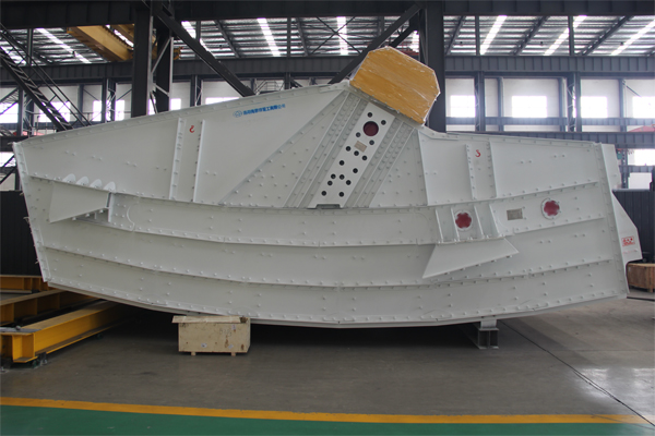
Single layer horizontal sieve

Understand Your Material:

Know the characteristics of the material you are screening. Consider factors such as particle size distribution, particle shape, moisture content, and density. Understanding your material is essential for selecting the right mesh size.

Determine the Required Separation or Classification:

Define your specific screening or classification objectives. Are you trying to remove oversize particles, separate fine materials, or achieve a specific particle size distribution?

Consider the Vibrating Screen Type:

Different types of vibrating screens have varying capabilities and limitations. For example, a linear vibrating screen may excel at dewatering, while a circular vibrating screen is suitable for general screening applications.

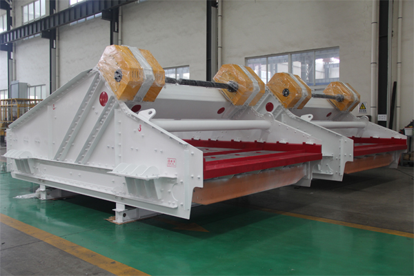
Double banana sieve

Calculate Particle Size Range:

Determine the minimum and maximum particle sizes that you need to screen or classify. This will help you select a mesh size range that can effectively achieve your goals.

Understand Mesh Size Terminology:

Familiarize yourself with mesh size terminology. Mesh size refers to the number of openings or wires per inch (25.4 millimeters) in a square inch of screen. Lower mesh numbers indicate larger openings, while higher mesh numbers indicate finer openings.

For more detailed information on how to choose the mesh size of the vibrating screen, please click here: https://www.hsd-industry.com/news/vibrating-screen-mesh-size-selection/

Valve bags, also known as valve sacks or open-mouth bags with a valve, are commonly used for packaging bulk materials such as cement, fertilizer, grains, and various powdered or granular products. These bags feature a one-way valve that allows for efficient and controlled filling and emptying of the contents.

Valve bag process flows

Bag Manufacturing:

The process begins with the manufacturing of valve bags. These bags are typically made of multi-layer paper, plastic, or a combination of both to provide strength and moisture resistance.

Printing and Labeling (Optional):

If branding, product information, or labels are required on the bags, printing and labeling can be done before they are sent to the filling facility.

Bag Storage:

Valve bags are stored in a clean and dry area until they are ready to be filled with the desired product.

Product Filling:

The product to be packaged is loaded into a hopper or filling machine.

The valve bag is placed onto the filling spout of the machine.

The product flows through the valve into the bag. The one-way valve prevents air from entering the bag during filling, allowing for efficient filling without the need for additional sealing.

Weighing and Dosing (Optional):

In some applications, the filling machine may include a weighing and dosing system to ensure that each bag contains the desired amount of product.

Bag Sealing and Closing:

After filling, the valve bag is carefully removed from the filling spout.

The bag’s valve closes automatically as it is removed from the spout, preventing any product from escaping.

Some valve bags may require additional sealing or stitching to ensure they are properly closed.

For more detailed information about the valve bag process flows, please click here: https://www.lyhuatianm.com/products-information/valve-bag-process-flow.html