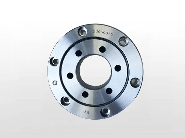
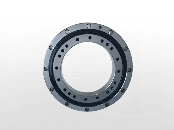
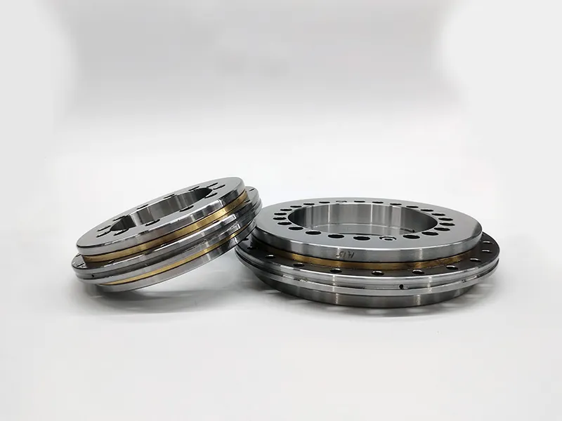
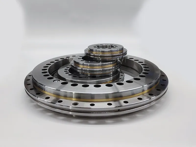
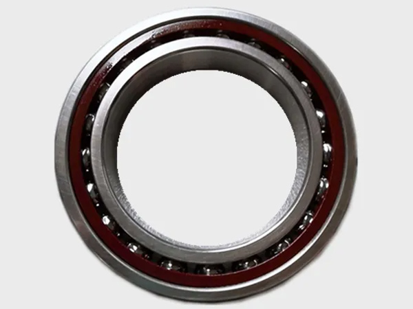
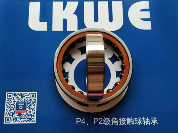
Crossed tapered roller bearings, also known as crossed roller bearings, are specialized bearings designed to provide high rotational accuracy and radial and axial stiffness. They are commonly used in applications where precise positioning and rotation are critical, such as machine tools, industrial robots, and rotary tables. Here are some key characteristics and features of crossed tapered roller bearings.

Crossed tapered roller bearings features

Crossed Tapered Roller Bearing

Crossed Design:

Crossed roller bearings have a unique design where cylindrical rollers are arranged in a crossed pattern between inner and outer rings. This arrangement allows for high rigidity and load-carrying capacity.

Tapered Rollers:

The rollers have tapered shapes, which helps distribute loads more evenly and accommodates both radial and axial forces.

High Rigidity:

The crossed arrangement of rollers provides high rigidity in both radial and axial directions, making these bearings suitable for applications with high precision and accuracy requirements.

Reduced Clearance:

Crossed tapered roller bearings often have preloaded or reduced clearance designs, minimizing backlash and improving positional accuracy.

Compact Design:

The compact design of crossed roller bearings allows them to accommodate heavy loads in a small envelope, making them suitable for applications where space is limited.

More detailed information on the performance of crossed tapered roller bearings can be found here:https://www.boyingbearing.com/en/a/news/crossed-tapered-roller-bearing-performance.html

Crossed cylindrical roller bearings, also known as crossed roller bearings, are a type of rolling element bearing designed to handle both radial and axial loads simultaneously. These bearings have cylindrical rollers arranged perpendicular to each other in a V-shaped groove, forming an X-shaped configuration. This design provides high rigidity and load-carrying capacity in a compact structure. There are several types of crossed cylindrical roller bearings, each with specific features and applications.

Crossed cylindrical roller bearing types

Crossed cylindrical roller bearings

Single Row Crossed Roller Bearings

This is the most basic type, consisting of a single row of cylindrical rollers with alternating orientations.

Suitable for applications with limited radial space and where high axial rigidity is required.

Commonly used in robot joints, industrial robots, and precision machinery.

Double Row Crossed Roller Bearings

In this type, two rows of cylindrical rollers are arranged in a crossed pattern.

Offers higher load-carrying capacity and increased rigidity compared to single row crossed roller bearings.

Used in applications where higher radial and axial loads need to be accommodated, such as machine tools and industrial robots.

Three Row Crossed Roller Bearings

Features three rows of cylindrical rollers arranged in a crossed pattern.

Provides even higher load capacity and stiffness compared to the double row design.

Commonly used in heavy-duty applications like construction machinery, industrial robots, and turntables.

Crossed cylindrical roller bearings

Separable Crossed Roller Bearings

This design allows the inner and outer rings to be separated, simplifying installation and maintenance.

Beneficial for applications where ease of assembly and disassembly is crucial.

More detailed information about crossed cylindrical roller bearing types can be found here: https://www.boyingbearing.com/en/a/news/crossed-cylindrical-roller-bearing-types.html

Operating a welding column and boom system requires careful attention to safety and precision. Below are general instructions for operating a welding column and boom. However, it’s crucial to consult the specific manual provided by the manufacturer of your equipment for detailed and accurate instructions tailored to your system.

Welding Column and Boom Operating Instructions

1. Safety Precautions

Before starting any welding operations, ensure that all safety procedures are followed.

Wear appropriate personal protective equipment (PPE), including welding helmets, gloves, and safety glasses.

Keep the work area well-ventilated to prevent the inhalation of fumes.

2. Equipment Inspection

Check the welding column and boom for any visible damage or signs of wear.

Inspect cables, hoses, and electrical connections for damage.

Ensure that all mechanical components, such as joints and motors, are in good working condition.

welding column and boom

3. Power On

Power on the welding column and boom according to the manufacturer’s instructions.

Verify that all control panels and displays are functioning properly.

4. Positioning

Use the control panel to position the welding boom accurately over the workpiece.

Ensure that the welding head is at the correct height and angle for the welding process.

5. Welding Parameters

Set the welding parameters, such as voltage, current, and wire feed speed, based on the welding procedure specifications.

Adjust the parameters as needed for different materials and joint configurations.

For more detailed information about the welding column boom operating instructions, please click to visit: https://www.bota-weld.com/en/a/news/welding-column-boom-operation.html

Welding rotators are essential equipment used in various industries for rotating cylindrical workpieces during welding or fabrication processes. The production process for welding rotators typically involves several key steps.

Welding rotator production process

Welding rotators

Design and Engineering

Begin with designing the welding rotator based on customer requirements, taking into account the size and weight of the workpieces to be rotated.

Consider factors such as load capacity, rotation speed, and the diameter range of workpieces.

Material Selection

Choose materials with high strength and durability for the main frame and rotating components. Common materials include steel alloys.

Cutting and Shaping

Use cutting machines, such as plasma or laser cutters, to shape the main components of the rotator, including the base, frame, and rotating rolls.

Welding

Assemble the cut components and weld them together using various welding techniques, such as MIG (Metal Inert Gas) or TIG (Tungsten Inert Gas) welding.

Ensure proper alignment and structural integrity during the welding process.

For more detailed information about the production process of welding rotator, please click here: https://www.bota-weld.com/en/a/news/welding-rotator-production-process.html

High-pressure Briquetting Machine Introduction

High-pressure briquetting machines have emerged as innovative solutions in the quest for sustainable waste management and efficient resource utilization. These machines play a pivotal role in converting various types of industrial and agricultural waste into compact, easy-to-transport, and energy-dense briquettes. This article explores the technical aspects and advancements in high-pressure briquetting machines, shedding light on their applications, working principles, and environmental benefits.

1. Working Principle

High-pressure briquetting machines utilize a dual-compaction process to transform raw materials into briquettes. The process involves applying intense pressure to compress the materials within a cylindrical chamber. This pressure induces plastic deformation in the material, causing it to bind together and form a cohesive briquette.

2. Components and Structure

Hydraulic System: The heart of a high-pressure briquetting machine is its hydraulic system. It consists of a hydraulic pump, control valves, and cylinders that generate and apply the necessary pressure for briquette formation.

Briquetting Chamber: The cylindrical chamber houses the raw material and facilitates the compaction process. It is designed to withstand high pressures and temperatures.

Feeding System: An efficient feeding system ensures a consistent and uniform supply of raw material to the briquetting chamber.

High-pressure briquetting machines

3. Material Compatibility

High-pressure briquetting machines can process a wide range of materials, including biomass residues, metal chips, and various industrial by-products. The versatility of these machines makes them invaluable in industries such as agriculture, metalworking, and manufacturing.

4. Applications

Biomass Briquetting: High-pressure briquetting machines are extensively used in the biomass industry to convert agricultural and forestry waste into biofuel briquettes. This process not only reduces waste but also provides a sustainable energy source.

Metal Chip Recycling: In metalworking industries, these machines compress metal chips and shavings into dense briquettes, facilitating easier handling, transportation, and recycling.

For more detailed information about the introduction of high-pressure briquetting machine, please click to visit:https://www.zymining.com/en/a/news/high-pressure-briquetting-machines.html

Briquetting machines are used to compress materials into compact, denser, and energy-dense briquettes. These machines play a crucial role in waste recycling, biomass energy production, and other applications. On the briquetting machine meaning page, we introduced the briquetting machine structure, technical parameters, solutions, price range and videos, etc. Next, we will continue to share with you the briquetting machine types, briquetting process, applications and briquetting. Let’s learn about the precautions and other contents together!

We have prepared a content directory for you.

Types of Briquetting Machines

Briquetting Processes

Uses of Briquetting Machines

Considerations for Briquetting

Types of Briquetting Machines

briquetting machine

Screw Type Briquette Machines

Use a screw to compress biomass or other materials into briquettes.

Commonly used for biomass, sawdust, and agricultural wastes.

Mechanical Stamping Briquette Machines

Utilize a stamping process to form briquettes.

Suitable for larger-scale production and a variety of materials.

Hydraulic Type Briquette Machines

Operate with hydraulic pressure to compress materials.

Suitable for high-pressure applications and a wide range of materials.

Piston Type Briquette Machines

Use a reciprocating piston to compress materials into briquettes.

Suitable for smaller-scale production.

For more detailed information about the briquetting machine guide, please click here: https://www.zymining.com/en/a/news/briquetting-machine-guide.html

Crossed cylindrical roller bearings, also known as crossed roller bearings, are a type of rolling element bearing designed to handle both radial and axial loads simultaneously. These bearings have cylindrical rollers arranged perpendicular to each other in a V-shaped groove, forming an X-shaped configuration. This design provides high rigidity and load-carrying capacity in a compact structure. There are several types of crossed cylindrical roller bearings, each with specific features and applications.

Crossed cylindrical roller bearing types

Crossed cylindrical roller bearings

Single Row Crossed Roller Bearings

This is the most basic type, consisting of a single row of cylindrical rollers with alternating orientations.

Suitable for applications with limited radial space and where high axial rigidity is required.

Commonly used in robot joints, industrial robots, and precision machinery.

Double Row Crossed Roller Bearings

In this type, two rows of cylindrical rollers are arranged in a crossed pattern.

Offers higher load-carrying capacity and increased rigidity compared to single row crossed roller bearings.

Used in applications where higher radial and axial loads need to be accommodated, such as machine tools and industrial robots.

Three Row Crossed Roller Bearings

Features three rows of cylindrical rollers arranged in a crossed pattern.

Provides even higher load capacity and stiffness compared to the double row design.

Commonly used in heavy-duty applications like construction machinery, industrial robots, and turntables.

For more detailed information about crossed cylindrical roller bearing types please click to visit: https://www.boyingbearing.com/en/a/news/crossed-cylindrical-roller-bearing-types.html

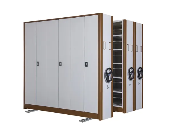
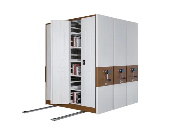
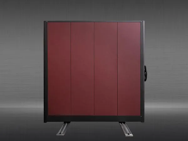
Mobile storage racks, also known as mobile shelving systems or compact shelving, represent a sophisticated solution to address the challenges of limited space and the need for efficient storage in various industries. These systems provide a dynamic and versatile approach to organizing and accessing stored items by maximizing space utilization and offering mobility features. Here is a detailed introduction to mobile storage racks, highlighting their features, benefits, and applications:

Key Features of Mobile Storage Racks

mobile shelving systems

Compact Design

Mobile storage racks are characterized by their compact design, which allows for a significant reduction in the amount of aisle space required compared to traditional static shelving.

High-Density Storage

The primary advantage of mobile storage racks is their ability to achieve high-density storage. By eliminating the need for fixed aisles, these systems make use of all available space, maximizing storage capacity.

Rail-Mounted System

Mobile racks are mounted on rails, enabling them to move horizontally along a track. This design facilitates easy access to any aisle by creating an opening where it is needed.

Manual or Powered Operation

Mobile storage racks can be operated manually by hand-crank systems or electronically with powered mechanisms. Powered systems are particularly beneficial for large installations and heavy loads, as they reduce manual effort.

Safety Features

To ensure user safety, mobile storage racks often come equipped with safety features such as anti-tip mechanisms, aisle entry sensors, and emergency stop buttons.

Customization Options

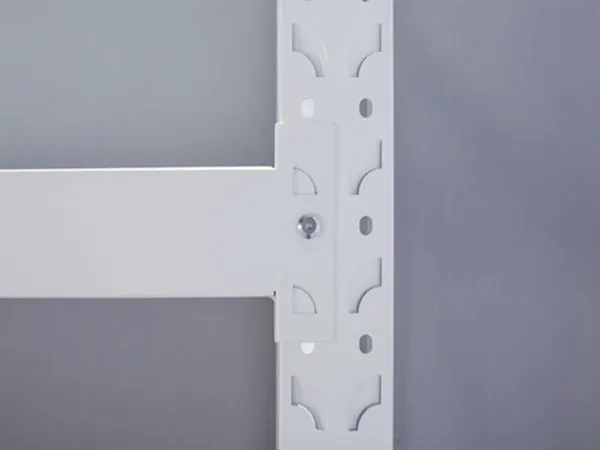
These systems are highly customizable to accommodate various storage needs. Shelves can be adjusted, and accessories such as dividers, bins, and labeling systems can be integrated.

For more information about the introduction of mobile storage racks, please click to visit: https://www.etegreen.com/en/a/news/introduction-to-mobile-storage-racks.html

Drawer tool cabinets, also known as tool chests or tool boxes with drawers, have become integral components in workshops, garages, and industrial settings. These cabinets provide a systematic and organized approach to tool storage, offering a secure and efficient way to store and access an array of tools. This technical article explores the key features, design considerations, and benefits of drawer tool cabinets.

Key Features of Drawer Tool Cabinets

Drawer tool cabinets

Durable Construction

Drawer tool cabinets are typically constructed from robust materials such as steel or aluminum to ensure durability and withstand the demands of heavy tool storage.

Multiple Drawers

One of the defining features is the presence of multiple drawers in various sizes. These drawers offer a segmented space for different tools, preventing clutter and facilitating easy organization.

Drawer Slides and Locking Mechanisms

High-quality drawer slides are crucial for smooth and effortless opening and closing of drawers. Locking mechanisms provide security for valuable tools and prevent unauthorized access.

Ball Bearing Drawer Slides

Many high-end drawer tool cabinets incorporate ball bearing drawer slides, which enhance the smooth operation of the drawers and contribute to the overall durability of the cabinet.

Powder-Coated Finish

A powder-coated finish not only adds an aesthetically pleasing touch but also provides corrosion resistance, extending the lifespan of the cabinet.

For more detailed information about the characteristics of drawer tool cabinets, please click to visit: https://www.rff-global.com/a/news/features-of-drawer-tool-cabinets.html

Slewing bearings, also known as turntable bearings or slewing rings, are specialized bearings designed to handle axial, radial, and moment loads simultaneously. They consist of an inner and outer ring, rolling elements, and sometimes gear teeth for gear-driven applications. Slewing bearings find application in a variety of industries due to their ability to support heavy loads, facilitate smooth rotation, and accommodate complex movements.

Slewing bearings applications

Slewing bearings

Construction Machinery

Excavators and Cranes: Slewing bearings are extensively used in excavators and cranes for their ability to support heavy loads and provide smooth rotation, allowing the equipment to turn and lift with precision.

Wind Turbines

Pitch and Yaw Systems: Slewing bearings are employed in the pitch and yaw systems of wind turbines. They allow the turbine blades to be adjusted for optimal wind capture (pitch control) and enable the entire turbine to rotate to face the wind (yaw control).

Mining Equipment

Bucket Wheel Excavators: Slewing bearings are used in bucket wheel excavators to facilitate the rotation of the massive bucket wheel, allowing efficient excavation in mining operations.

Material Handling Equipment

Cranes and Conveyor Systems: Slewing bearings play a critical role in cranes and conveyor systems, enabling the rotation of the load and facilitating the movement of materials in various directions.

Robotics

Industrial Robots: Slewing bearings are integral components in the joints of industrial robots. They enable precise and controlled movement, allowing robots to perform tasks with accuracy in manufacturing processes.

Aerospace

Satellite and Radar Systems: Slewing bearings are used in satellite and radar systems to facilitate the rotation of antennas and sensors, allowing them to track celestial bodies or monitor specific areas.

For more detailed information about the application fields of slewing bearings, please click to visit: https://www.prsbearings.com/a/news/slewing-bearings-application.html