A single plate clutch is a type of friction clutch commonly used in automotive applications. It serves the purpose of engaging and disengaging the transmission from the engine to allow for smooth gear changes. Here are some key applications and features of single plate clutches.

Single plate clutch application

MF series

Automotive Vehicles

Cars and Trucks: Single plate clutches are widely used in manual transmission vehicles, where the driver needs to manually shift gears. The clutch enables the temporary disconnection of the engine from the gearbox, allowing for gear changes.

Motorcycles

Motorcycles and Scooters: Single plate clutches are commonly found in motorcycles, providing a compact and efficient solution for transmitting power from the engine to the gearbox.

Industrial Machinery

Power Transmission: In various industrial applications, single plate clutches are used for power transmission between a prime mover (like an electric motor) and a driven machine. They can be employed in situations where controlled engagement and disengagement of power transmission are required.

12 Inch 26 Spline

Agricultural Equipment

Tractors and Agricultural Machinery: Some agricultural vehicles and machinery use single plate clutches to transmit power from the engine to the transmission. Clutches in this context are important for controlling the movement of the vehicle and its various components.

Construction Equipment

Construction Vehicles and Equipment: Single plate clutches can be found in certain types of construction equipment, particularly those with manual transmissions. They play a role in controlling the power flow from the engine to the drivetrain.

For more detailed information about the application fields of single plate clutch, please click here: https://www.syclutch.com/news/single-plate-clutch-application.html

The tractor clutch system is a crucial component in a tractor’s drivetrain, providing a means to engage and disengage power between the engine and the transmission. It allows the operator to control the transfer of power from the engine to the wheels, facilitating smooth starts, stops, and gear changes. Understanding the tractor clutch system involves recognizing its components, functions, and the overall mechanism by which it operates.

Components of a Tractor Clutch System

MF series

Clutch Pedal

The clutch pedal is located in the tractor’s operator compartment and is used by the operator to engage and disengage the clutch. Pressing the pedal activates the clutch mechanism.

Clutch Disc

The clutch disc, also known as the friction disc, is positioned between the flywheel and the pressure plate. It consists of friction material on both sides and is responsible for transmitting power from the engine to the transmission.

Flywheel

The flywheel is attached to the rear of the engine and provides a rotating mass. It also serves as a mounting surface for the clutch assembly. The energy stored in the flywheel helps to smooth out engine power fluctuations.

Pressure Plate

The pressure plate is bolted to the flywheel and exerts pressure on the clutch disc when engaged. This pressure brings the clutch disc into contact with the flywheel, allowing power transfer.

Release/Throw-Out Bearing

The release bearing, also known as the throw-out bearing, is located on the transmission input shaft. When the clutch pedal is depressed, the release bearing moves towards the pressure plate, disengaging the clutch.

Clutch Housing

The clutch housing contains the clutch assembly and is mounted between the engine and the transmission. It provides protection and support for the clutch components.

How the Tractor Clutch System Works

NH series

Engagement

When the operator releases the clutch pedal, the pressure plate applies force to the clutch disc against the flywheel. This engagement allows power to transfer from the engine to the transmission, enabling the tractor to move.

For more detailed information about the clutch system, please click here: https://www.syclutch.com/news/introduction-to-tractor-clutch-system.html

Clutches are mechanical devices used to engage and disengage power transmission between two rotating shafts. They play a crucial role in various machines and vehicles, allowing the user to control the transfer of power. There are several types of clutches, each with its own design and working principle.

The common types of clutches and how they work

K series

Friction Clutch

Working Principle: Friction clutches operate on the principle of friction between two surfaces. They consist of a driving member (usually a flywheel) and a driven member (usually a pressure plate), with friction material sandwiched between them.

Engagement: When the clutch is engaged, pressure is applied to bring the friction surfaces together, allowing power transfer.

Disengagement: To disengage the clutch, the pressure is released, creating a gap between the friction surfaces and interrupting power transmission.

Single Plate Clutch

Construction: Consists of a single friction plate sandwiched between the flywheel and the pressure plate.

Operation: Engages and disengages by pressing the friction plate against the flywheel with the help of a release bearing and a diaphragm spring or coil spring mechanism.

12 Inch 26 Spline

Multi-Plate Clutch

Construction: Uses multiple friction plates alternately interleaved with steel plates.

Operation: Similar to a single plate clutch but offers greater torque capacity due to increased friction surface area.

Cone Clutch

Working Principle: Involves conical surfaces on the driving and driven members. Engaging the clutch brings these conical surfaces into contact, creating friction for power transfer.

Use: Commonly used in small motor vehicles.

For more detailed information about clutch types and working principles, please click here:https://www.syclutch.com/news/clutch-types-and-working-principles.html

The capacity of a vibrating screen is a measure of the amount of material that can be processed or screened in a given time period. It is usually expressed as tons per hour (tph) or cubic meters per hour (m³/h), depending on the unit of measurement used. The capacity of a vibrating screen depends on several factors, including:

Screen Size and Surface Area: Larger screens and greater surface areas can handle more material.

Screen Deck Configuration: The number of decks on a vibrating screen can affect its capacity. Multiple decks allow for the sorting of different particle sizes.

Screen Motion: The type of motion of the vibrating screen, such as linear, circular, or elliptical, can impact its capacity. Different motions are suitable for different types of applications.

Screen Slope: The angle of the screen deck also plays a role. Steeper slopes generally allow for better material separation but can reduce capacity.

Material Characteristics: The type, size, and characteristics of the material being screened influence the capacity. For example, wet or sticky materials may require a different type of screen or additional equipment for effective screening.

Vibration Frequency and Amplitude: The frequency (cycles per minute) and amplitude (the height of the vibrating motion) can be adjusted to optimize the screening process for different materials.

Feed Rate: The rate at which material is fed onto the screen affects the screening capacity. Proper feed rates help ensure optimal performance.

Screening Efficiency: The efficiency of the screening process also affects capacity. Higher efficiency means more effective screening and potentially higher throughput.

Vibrating screen capacity calculation

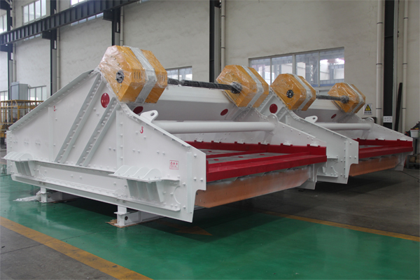
Arc Vibrating Screen

The capacity of a vibrating screen is typically represented by the throughput or the flow rate of material through the screen. The capacity calculation depends on various factors, including the screen dimensions, screen inclination, and the characteristics of the material being screened. Here’s a general approach to calculating the capacity of a vibrating screen:

1. Basic Formula:

The basic formula for calculating the capacity of a vibrating screen is:

Where:

  • is the capacity (throughput) in tons per hour.
  • is the effective screening area (in square feet).
  • is the percentage of material in the feed to the screen that is smaller than the screen opening size.
  • is the basic capacity of the screen in tons per hour per square foot.
  • is the efficiency factor, which is typically in the range of 90-95%.
  • is a correction factor that depends on the type of screen and the material being screened.

For more detailed information on how to increase vibrating screen capacity, please click here: https://www.hsd-industry.com/news/vibrating-screen-capacity/

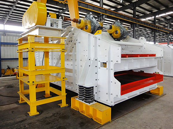
A linear vibrating screen is a type of vibrating screen machine used for screening and grading materials in various industries. It employs a linear motion to convey materials along the vibrating surface, providing efficient and effective screening of granular and bulk materials. Here’s a detailed introduction to the linear vibrating screen.

Key Components of a Linear Vibrating Screen

Single layer horizontal sieve

Screen Surface

The screen surface is the primary component where the material separation takes place. It is typically made of wire mesh or perforated plates with specific opening sizes to allow particles of desired sizes to pass through.

Vibrator Motors

The linear vibrating screen is equipped with one or multiple vibrator motors that generate the vibration required for material movement. These motors are mounted on the screen frame and provide the necessary linear vibration.

Screen Frame

The screen frame supports the screen surface and vibrator motors. It is designed to withstand the dynamic forces generated during the screening process. The frame may be constructed from steel or other materials depending on the application.

Springs or Rubber Mounts

To isolate the vibrations generated by the vibrator motors, linear vibrating screens often use springs or rubber mounts. These components absorb and dampen the vibrations, preventing excessive transmission to the supporting structure.

Feed Inlet and Discharge Chutes

The linear vibrating screen has designated areas for material entry (feed inlet) and exit (discharge chute). The material is usually fed onto the screen surface through the feed inlet, and the screened material exits through the discharge chute.

Drive Unit

The drive unit includes the motor(s), which generate the linear vibration, and may also include other components like belts or gears depending on the specific design of the linear vibrating screen.

Operating Principle

Linear Vibrating Screen

Vibration Generation

The vibrator motors generate linear vibrations that cause the screen surface to move along a straight line. This motion helps convey and separate the material based on size.

Material Feed

Material is introduced onto the vibrating screen surface through the feed inlet. The linear motion of the screen surface moves the material along the length of the screen.

Screening Process

As the material travels along the vibrating surface, particles that are smaller than the openings in the screen pass through, while larger particles are retained. This process effectively separates materials into different size fractions.

For more detailed information about linear vibrating screen, please click to visit: https://www.hsd-industry.com/news/introduction-to-linear-vibrating-screen/

A vibrating screen is a mechanical equipment used for separating materials into smaller-sized fractions or removing impurities. It consists of a screen mesh, which is a surface with openings of specific sizes, through which materials pass when subjected to vibration. Vibrating screens find applications in various industries, including mining, construction, agriculture, and recycling.

Components of a Vibrating Screen

Screen Mesh:

The screen mesh is a critical component with openings that determine the size of particles passing through. Different types of screen meshes, such as woven wire mesh or perforated plates, may be used based on the application.

Vibrator Motors:

Vibrating screens are equipped with one or more vibrator motors that generate the vibratory motion. These motors are mounted on the sides or underneath the screen deck.

Screen Deck:

The screen deck is the surface on which the material is placed for screening. It can have one or multiple layers, each with a different mesh size.

Support Structure:

The support structure provides stability and ensures proper alignment of the vibrating screen components. It may include a frame, springs, and other structural elements.

Drive Unit:

The drive unit is responsible for generating the necessary vibration to move the screen. It typically includes an electric motor, an eccentric shaft, and a set of gears.

Working Principle

The vibrator motors generate vibratory motion, causing the screen deck to vibrate. This vibration moves the material along the screen surface and separates particles based on size or other characteristics. The inclination and amplitude of the vibrating screen can be adjusted to optimize the screening process for specific applications.

High Frequency Dehydration Vibrating Screen

Screening Area Calculation:

  • The screening area is the total available surface area of a screening deck.
  • Calculate the screening area by multiplying the length of the screen (L) by the width of the screen (W).

Deck Surface Opening:

The size of the openings in the screening surface affects the efficiency of the screening process.

Specify the desired opening size or use the average particle size of the material being screened.

Vibration Amplitude:

Vibration amplitude is the measure of the amount of vibrational movement the screen deck undergoes during operation.

It is typically expressed in millimeters (mm) or inches (in).

The amplitude can be determined based on the type of vibrating screen and the material being processed.

For more detailed information about vibrating screen parameter calculation, please click here: https://www.hsd-industry.com/news/vibrating-screen-parameter-calculation/

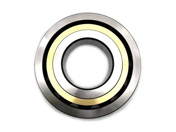
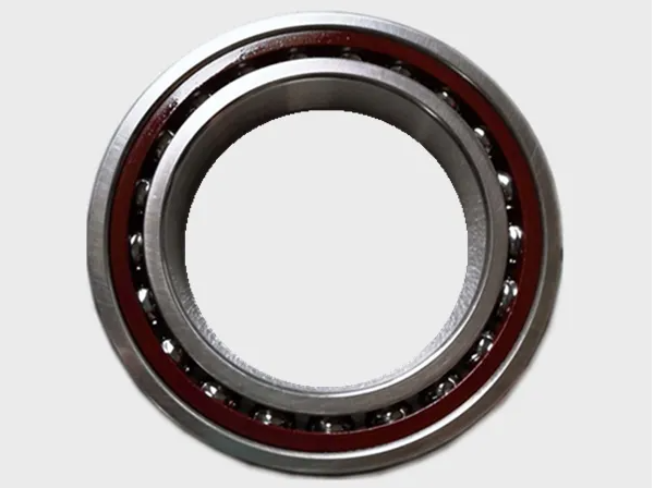
LYLKWE spindle bearings are universal bearings, and the bearing rings have the same width. The protrusions on both sides of the bearing are the same size.

Advantages of universal matched bearings

Individual bearings can be installed in any bearing arrangement required, such as X-shaped, O-shaped or tandem arrangements with rigid or elastic preload, or can be combined in different bearing groups.

In a tandem bearing arrangement, in order to ensure that the bearings carry a consistent load, the bearings being paired have the same dimensional deviation between the inner and outer diameters.

In a rigidly adjusted O-ring arrangement, grouping detection of interference between the shaft and bearing bore diameters or housing and bearing outside diameters can help control changes in actual preload after the bearing is installed.

Bearings can be arranged according to the direction of the arrow on the outer ring surface.

Universal matching bearing set

The universal matched bearing set is composed of universal matched bearings with the same bearing inner diameter deviation and the same bearing outer diameter deviation.

The dimensional deviation represents the actual size code, which is the deviation value of the inner diameter or outer diameter marked on the bearing ring.

The universal matched bearing set is composed of multiple bearings with the same technical quality and the same bearing inner diameter deviation and bearing outer diameter deviation.

Bearing group identification

The first letter indicates the number of paired bearings:

D=2 bearings (double)

T=3 bearing (triple)

Q=4 bearings (quadruple).

“U” means “universal pairing” such as DU. After these letters, there is an indication of the preload level, such as DUL, where “L” means light preload.

Universal bearing sets can be installed in any required bearing arrangement.

For more detailed information about spindle bearing models and selection, please click to visit:https://www.lkwebearing.com/news-center/spindle-bearing-selection.html

There are many types of bearings, and there are countless bearings that can be used for machine tool spindles. However, for CNC machine tools, the selection of spindle bearings is not like that of ordinary machine tools. The various requirements are more stringent. Different CNC machine tool spindle bearing selections Different priorities that need to be considered when selecting CNC machine tool spindle bearings often lead to very different bearing types. The following spindle bearing manufacturers have compiled the CNC machine tool spindle bearing selection principles and guidelines for your reference.

CNC machine tool spindle bearing selection principles

The selection principle of CNC machine tool spindle bearings is to use different types of bearings according to the different requirements of the spindle assembly such as rotation speed, load-bearing capacity and rotation accuracy:

1. Generally, the spindle components of small and medium-sized CNC machine tools (lathes, milling machines, machining centers, grinders) mostly use rolling bearings;

2. Heavy-duty CNC machine tools use hydrostatic bearings;

3. High-precision CNC machine tools (such as coordinate grinders) use gas static pressure bearings;

4. The spindle with a speed of (2-10)x104r/min can use magnetic bearings or ceramic rolling bearings.

In actual use, reasonable selection should be made based on comprehensive consideration of the working performance requirements, manufacturing conditions and economic effects of the spindle assembly.

For more detailed information on CNC machine tool spindle bearing selection, click to visit: https://www.lkwebearing.com/news-center/machine-tool-spindle-bearing-selection.html

The protrusion amount of the angular contact ball is also called the grinding amount. It is calculated in a scientific way. When back-to-back, face-to-face or combined, through installation and extrusion, the calculated optimal preload amount and free play are calculated. Clearance value, so the bearing can maximize the design upper limit, which is convenient for users.

Measuring the protrusion of angular contact ball bearings is crucial for ensuring proper functioning and alignment in various applications, such as machinery and automotive systems. The protrusion measurement is typically done to ensure that the bearings are correctly seated and that there is proper contact between the bearing and its mating components. Here’s a general method and principle for measuring the protrusion of angular contact ball bearings:

Angular contact ball bearing protrusion measurement method:

Equipment Setup

  • Use a measuring instrument such as a caliper or a micrometer.
  • Ensure the measuring instrument is calibrated and in good condition.
  • Prepare a flat and clean surface for the bearing and mating components.

Positioning the Bearing

  • Mount the angular contact ball bearing in its intended location within the machinery or assembly.
  • Ensure that the bearing is properly seated and aligned according to the design specifications.

Selection of Measurement Points

  • Identify the specific points on the bearing or its housing where protrusion measurements are required.
  • These points are typically defined in the engineering or assembly specifications.

Taking Measurements

  • Place the measuring instrument perpendicular to the surface of interest.
  • Gently touch the measuring instrument to the designated points on the bearing or its mating component.
  • Record the measurements carefully.

Repeat Measurements

  • Take multiple measurements at different points to ensure accuracy and consistency.
  • Calculate the average protrusion value if multiple measurements are taken.
  • Comparison with Specifications:
  • Compare the measured protrusion values with the design or assembly specifications.
  • Ensure that the measurements fall within the specified tolerances.

For more detailed information about the crown measurement method and principle of angular contact ball bearings, please click to visit: https://www.lkwebearing.com/news-center/angular-contact-ball-bearing-measurement-methods.html

A tandem thrust cylindrical roller bearing is a type of bearing designed to handle axial loads in both directions. Unlike radial bearings, which primarily support radial loads (perpendicular to the shaft), thrust bearings support axial loads (parallel to the shaft). Tandem thrust bearings are specifically configured to handle heavy axial loads and provide high rigidity.

In a tandem thrust cylindrical roller bearing, two or more cylindrical roller thrust bearings are arranged in tandem (one after the other) along the shaft axis. This arrangement allows the bearing to support axial loads from both directions. Cylindrical roller thrust bearings consist of small cylindrical rollers arranged in a cage, which are guided between the bearing’s raceways.

The tandem configuration enhances the bearing’s load-carrying capacity and stiffness, making it suitable for applications where high axial loads and precise axial positioning are required. These bearings are commonly used in various industrial applications, such as machine tools, gearboxes, and large pumps, where axial loads need to be supported reliably and efficiently.

Tandem thrust cylindrical roller bearing applications

Machine Tool Spindles

Tandem thrust bearings are often employed in machine tool spindles to handle the axial loads generated during machining operations. The compact design of tandem bearings makes them suitable for this application where space constraints are critical.

Gearboxes

In heavy machinery and industrial gearboxes, tandem thrust bearings can support the axial loads generated by gears and other rotating components. Their ability to handle high axial loads makes them essential in ensuring the smooth operation of gear systems.

Extruders

Extruders used in plastic and rubber processing industries often require bearings that can withstand significant axial forces. Tandem thrust cylindrical roller bearings are well-suited for handling the axial loads encountered in extrusion processes.

Pumps

Centrifugal pumps and other types of industrial pumps require bearings that can endure both radial and axial loads. Tandem thrust bearings are utilized in pump applications where axial loads are predominant.

Steel Industry

Tandem thrust bearings are commonly used in the steel industry, particularly in applications like rolling mills where heavy axial loads are present due to the rolling process.

For more detailed information about the application fields of tandem thrust cylindrical roller bearings, please click to visit: https://www.lkwebearing.com/news-center/tandem-thrust-cylindrical-roller-bearing-applications.html