A welding positioner is a mechanical device used to manipulate and hold a workpiece in the optimal position for welding. It allows welders to work more efficiently by rotating or tilting the workpiece to the desired angle, making it easier to access different areas for welding without having to reposition themselves constantly.

Welding positioners come in various shapes and sizes, ranging from small tabletop units for light-duty welding to large, heavy-duty units capable of handling massive workpieces in industrial settings. They typically consist of a base, a rotating mechanism, and a fixture to hold the workpiece securely in place. Some advanced positioners may also include tilting capabilities to achieve even more precise positioning.

Using a welding positioner can improve weld quality, increase productivity, and reduce fatigue for the welder by providing better access to the welding area and allowing for consistent weld bead placement.

Welding positioner type

welding positioner

Horizontal Positioners: These positioners rotate the workpiece around a horizontal axis. They are often used for welding cylindrical or round workpieces such as pipes, tanks, and vessels.

Vertical Positioners: These positioners rotate the workpiece around a vertical axis. They are suitable for welding flat or plate-like workpieces and are commonly used in industries such as shipbuilding and construction.

Headstock-Tailstock Positioners: These positioners consist of a headstock (which holds one end of the workpiece) and a tailstock (which supports the other end). They allow for rotation and tilting of the workpiece, providing greater flexibility in positioning during welding.

Turntable Positioners: Turntable positioners are like rotating platforms that can hold and rotate the workpiece. They are often used for smaller workpieces and in situations where precise rotation is required.

Manipulators: Manipulators are more complex positioners that combine vertical and horizontal movement capabilities. They can move the welding torch in multiple directions around the workpiece, allowing for welding in various positions and angles.

Automatic Welding Positioners: These positioners are equipped with automation features such as programmable controls, sensors, and robotic arms. They are used in automated welding processes where precise control and repeatability are essential.

For more detailed information about what a welding positioner is, click to visit: https://www.bota-weld.com/en/a/news/what-is-a-welding-positioner.html

The welding turntable is a versatile tool used in various welding applications to improve productivity, enhance weld quality, and ensure operator safety.

Purpose and Benefits

The welding turntable, also known as a rotary welding positioner, serves a critical role in welding processes by enabling controlled rotation of the workpiece or welding gun. This rotation facilitates access to all sides of the workpiece without manual repositioning, thereby streamlining welding operations. Some key benefits of using our welding turntable include:

Enhanced Weld Quality: The consistent rotation provided by the turntable ensures uniform heat distribution and deposition of weld material, resulting in high-quality, defect-free welds.

Increased Productivity: By eliminating the need for manual repositioning of the workpiece, our welding turntable reduces downtime and allows for continuous welding, leading to faster completion of projects.

Operator Safety and Comfort: The ergonomic design of the turntable minimizes strain on operators by eliminating the need for repetitive manual handling of heavy or awkward workpieces. This helps prevent fatigue and reduces the risk of musculoskeletal injuries.

welding turntable

Welding Turntable Basic Operation

Operating our welding turntable is straightforward, but it requires proper setup and adherence to safety procedures. Here’s a brief overview of the basic operation:

Setup: Securely mount the workpiece or welding gun onto the turntable, ensuring proper alignment and balance to achieve optimal welding results.

Power On: Activate the turntable’s power supply and control panel, following any specific startup procedures outlined in the user manual.

Adjust Rotation Speed and Direction: Use the control panel to adjust the rotation speed and direction according to the welding requirements and specifications of the workpiece.

Perform Welding: Initiate the welding process using the appropriate welding equipment (e.g., MIG, TIG, or stick welder), while the turntable rotates the workpiece. Monitor the welding operation to ensure proper weld bead deposition.

For more detailed information about welding turntable operation, please click here: https://www.bota-weld.com/en/a/news/welding-turntable-operation.html

The price of a metal briquetting machine can vary widely depending on several factors, including the type of machine, its capacity, features, and the manufacturer or supplier. Metal briquetting machines are used to compress metal chips or shavings into compact and dense briquettes, making it easier to handle, transport, and recycle metal waste.

Factors affecting the price of metal briquetting machine

metal briquetting machine

Machine Type

There are different types of metal briquetting machines, such as hydraulic briquetting machines, mechanical briquetting machines, and screw-type briquetting machines. Each type has its own set of features and capabilities, and their costs can vary.

Capacity

The capacity of the machine, which refers to the amount of metal it can process and compress in a given time, is a significant factor. Higher capacity machines generally come with a higher price tag.

Automation and Features

Machines with advanced features, automation, and user-friendly controls may cost more than basic models. Automation can enhance efficiency and reduce labor requirements.

Manufacturer and Brand

Different manufacturers and brands may offer machines with varying specifications and quality. Well-established and reputable manufacturers might charge higher prices for their machines.

metal briquetting machine

Market Conditions

Market conditions, including supply and demand dynamics, economic factors, and competition, can influence the pricing of metal briquetting machines.

Additional Equipment and Accessories

Some machines may come with additional equipment or accessories, such as cooling systems, chip crushers, or conveyors, which can affect the overall cost.

For more detailed information on the factors affecting the price of metal briquetting machines, please click here: https://www.zymining.com/en/a/news/factors-affecting-the-price-of-metal-briquetting-machine.html

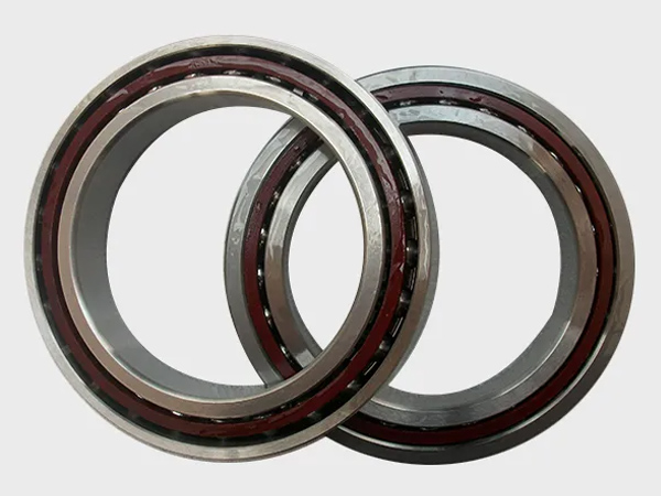
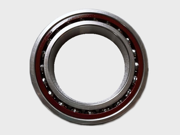
Installing rotary table bearings involves careful handling and precise procedures to ensure the proper functioning of the rotary table. Rotary tables are commonly used in machining applications for indexing and positioning workpieces. The installation process may vary depending on the specific design and type of rotary table bearings.

Rotary table bearing installation process

rotary table bearings

  • Tools and Equipment
  • Appropriate lifting equipment (if the rotary table is heavy).
  • Clean workspace and surface.
  • Torque wrench.
  • Bearings and associated components.
  • Lubricants specified by the manufacturer.
  • Alignment tools.

Rotary table bearing installation steps:

rotary table bearings

1. Prepare the Workspace:

  • Ensure that the installation area is clean and free of debris.
  • Make sure the rotary table and associated components are easily accessible.
  • Use appropriate lifting equipment if the rotary table is heavy.

2. Inspect Bearings and Components:

  • Inspect the rotary table bearings and associated components for any damage or defects.
  • Ensure that all components are clean and free from contaminants.

3. Apply Lubrication:

  • Apply the specified lubricants to the bearing surfaces as recommended by the manufacturer.
  • Ensure that the lubricant is evenly distributed and provides proper coverage.

4. Position the Rotary Table:

  • Carefully position the rotary table in the desired location.
  • Use alignment tools to ensure the table is properly aligned with other components or machine elements.

For more detailed information about the installation of the rotary table, please click here: https://www.boyingbearing.com/en/a/news/rotary-bearing-installation.html

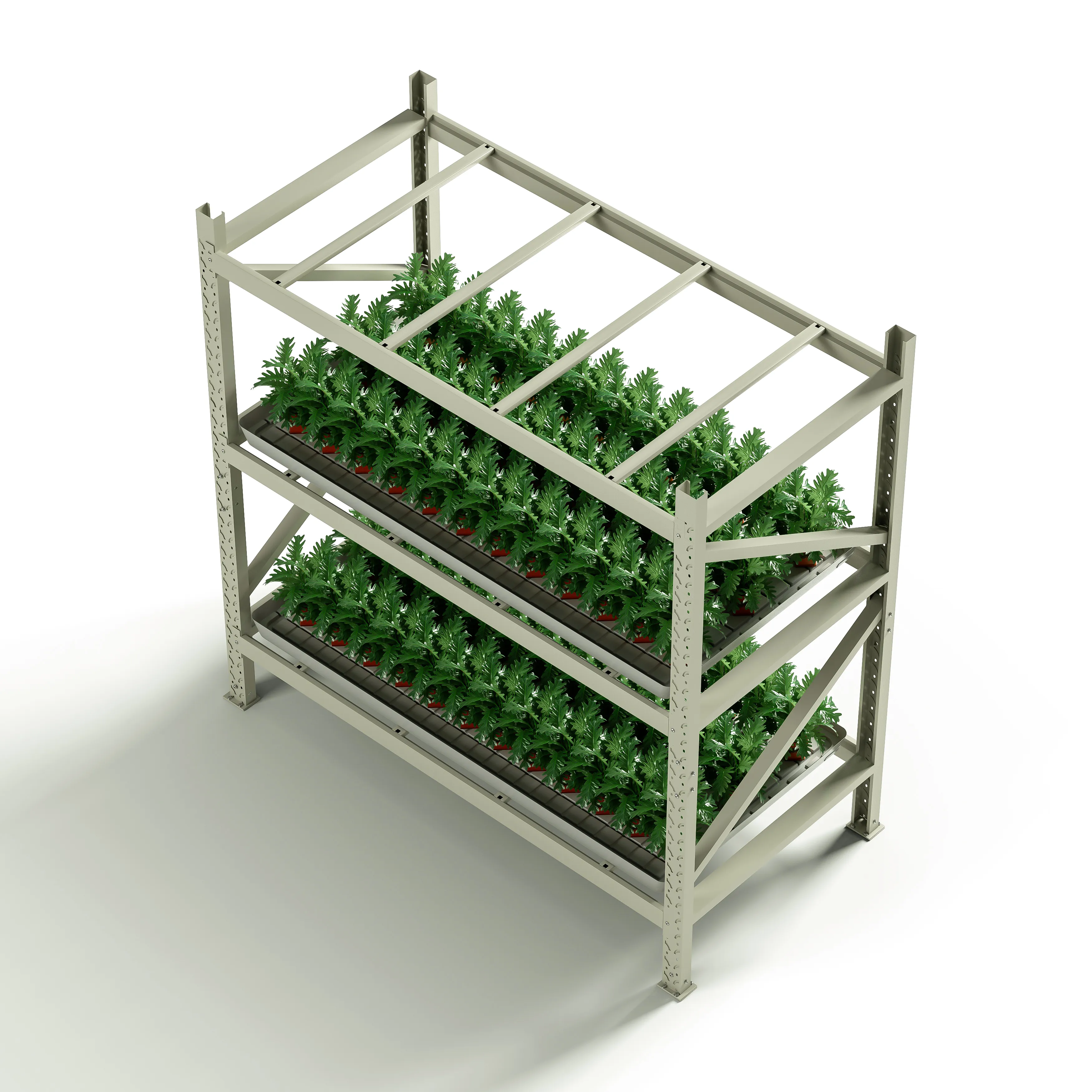
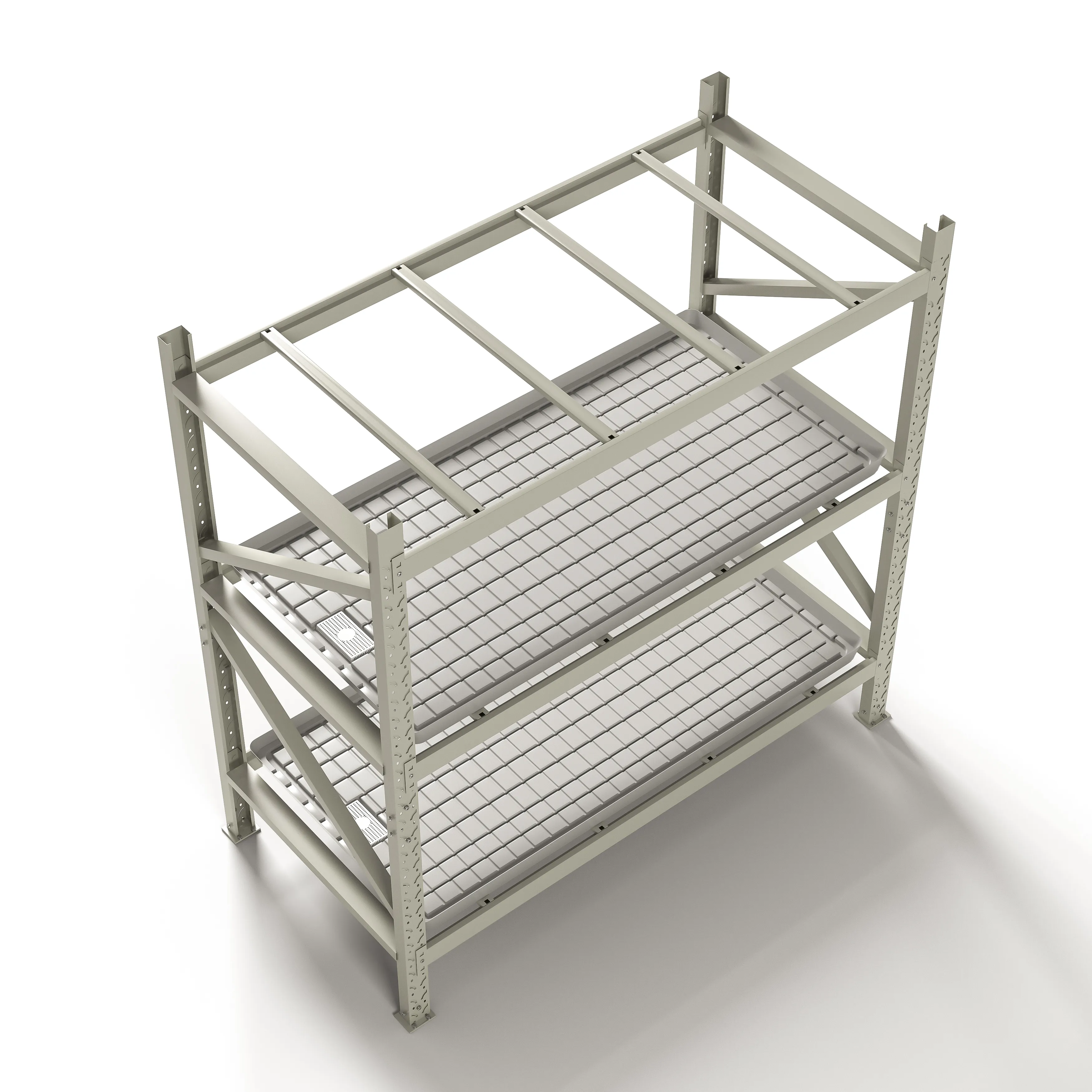
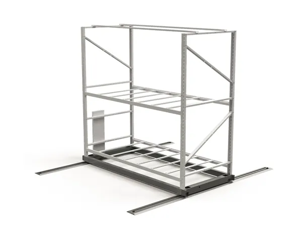
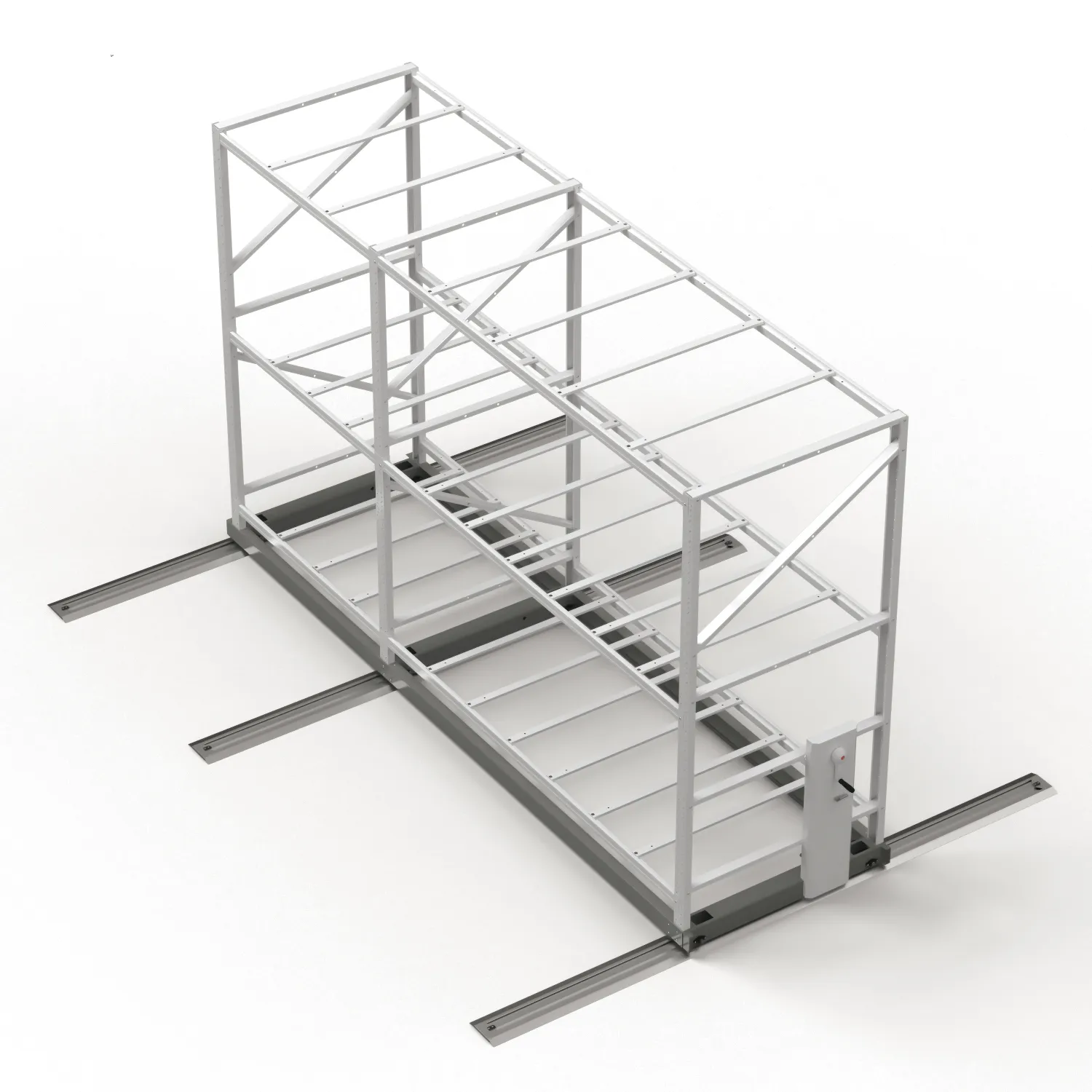
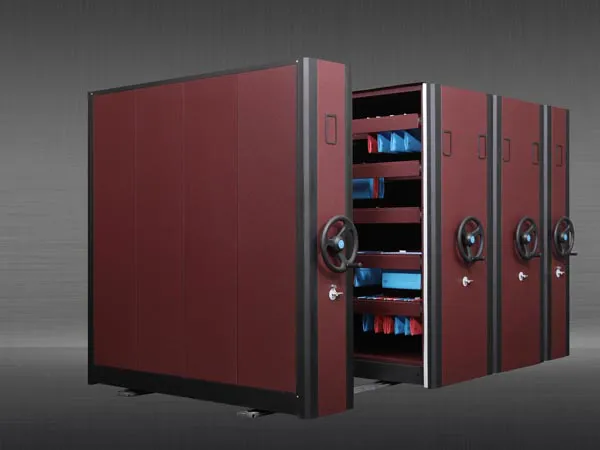
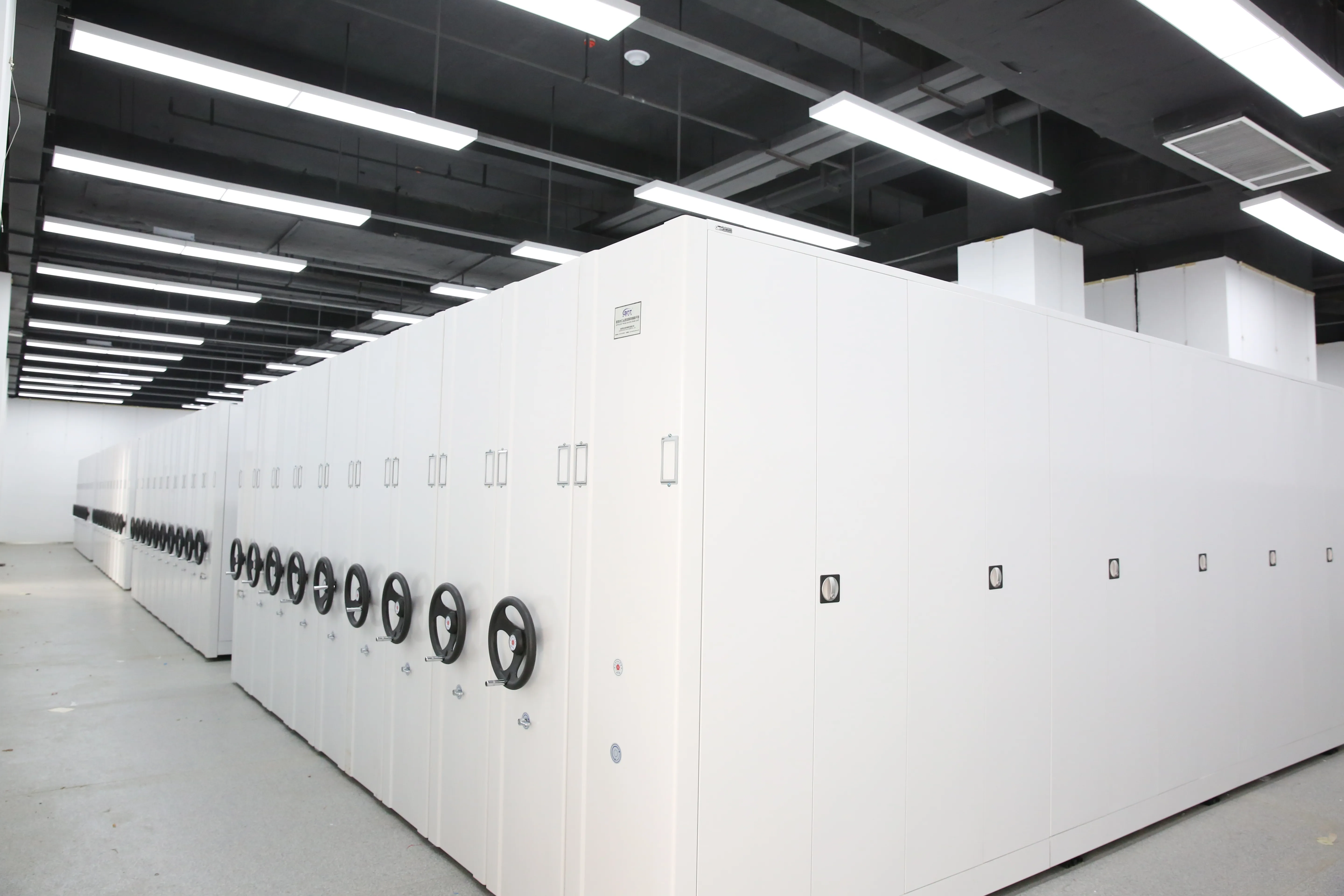
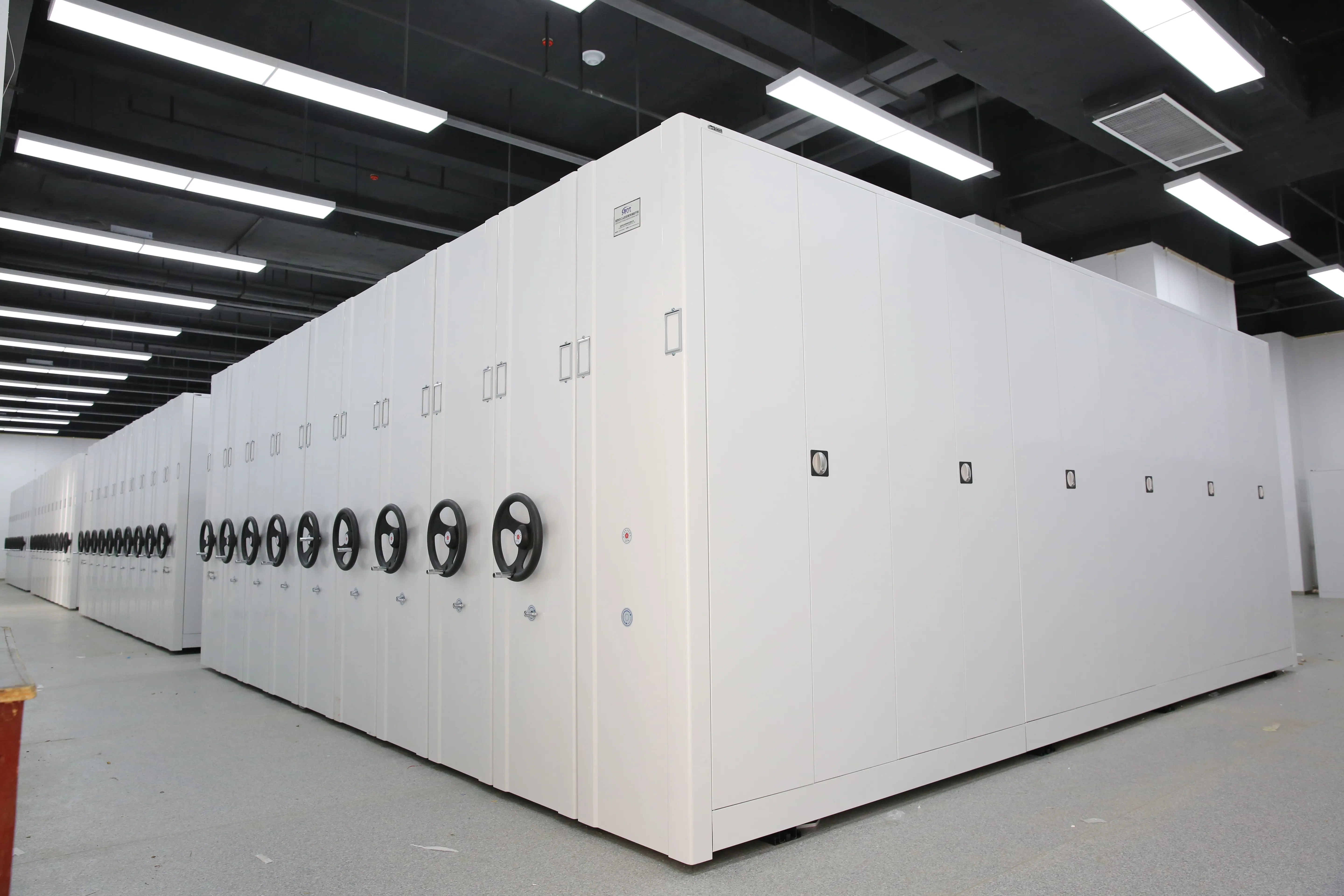
Mobile storage shelves typically refer to shelving units or systems that are designed to be mobile or easily movable. These storage solutions are commonly used in various settings, such as offices, libraries, warehouses, healthcare facilities, and more. The mobility of these shelves is often achieved through the use of wheels or casters, allowing the entire shelving unit to be easily repositioned as needed.

Mobile Storage Shelves Composition

Mobile storage shelves

Shelving Material

  • Steel: Many mobile storage shelves are constructed using steel. Steel is a durable and robust material that provides strength to the shelves, allowing them to support heavy loads.
  • Aluminum: In some cases, aluminum may be used for its lightweight properties. While not as heavy-duty as steel, aluminum can still offer strength and resistance to corrosion.

Shelving Surfaces:

  • Laminates: Shelves may feature laminated surfaces for a smooth and easy-to-clean finish. Laminates can also add an aesthetic touch to the shelving system.
  • Powder Coating: Steel components are often powder-coated for enhanced durability, corrosion resistance, and an appealing finish.

Frame Structure:

  • Steel Frames: The frames that support the shelves are typically made of steel for stability and load-bearing capacity.
  • Rolling Mechanism: Mobile storage shelves often have a rolling or sliding mechanism that allows them to be easily moved along tracks. This mechanism may include wheels or bearings for smooth mobility.

Tracks and Rails:

  • Steel Tracks: The tracks or rails on which the mobile shelves move are commonly made of steel. These tracks are crucial for the smooth and efficient operation of the mobile shelving system.

Handles and Controls:

  • Ergonomic Handles: Handles for moving and accessing the shelves are often designed to be ergonomic for ease of use. They may be made of materials such as plastic or rubber for a comfortable grip.
  • Control Mechanisms: Mobile storage systems may include controls for locking, unlocking, and moving the shelves. These controls are usually designed to be user-friendly.

Finishing and Coating:

  • Anti-corrosion Coating: Steel components may have anti-corrosion coatings to protect them from rust and other environmental factors.
  • Paint or Finish: Aesthetic considerations may involve painting or finishing the steel components to match the overall design or color scheme.

Adjustability:

  • Adjustable Shelves: Some mobile storage shelves allow for shelf height adjustment to accommodate different types of items or changing storage needs.

Safety Features:

  • Locking Mechanisms: Mobile storage shelves often include locking mechanisms to secure the shelves in place when needed, preventing unintentional movement.
  • Safety Sensors: Some systems may feature safety sensors to detect obstacles or obstructions in the path of moving shelves, ensuring safe operation.

For more detailed information about mobile storage shelves, please click here: https://www.etegreen.com/en/a/news/mobile-storage-shelves-introduction.html

A drawer tool cabinet, also known as a tool chest or tool cabinet, is a storage unit designed to organize and store tools in a workshop or garage. It typically consists of multiple drawers and compartments of varying sizes, providing a secure and organized space for storing hand tools, power tools, and other equipment.

Components of a drawer tool cabinet

drawer tool cabinet

Materials and Construction

Tool cabinets are commonly made of metal, such as steel or aluminum, to ensure durability and strength. The construction should be sturdy and well-built to withstand the weight of tools and regular usage in a workshop environment.

Drawers

The primary feature of a drawer tool cabinet is its multiple drawers. These drawers come in various sizes to accommodate different types of tools. The drawers are often equipped with ball-bearing slides or other mechanisms to allow smooth and easy opening and closing.

Locking Mechanism

Many tool cabinets come with a locking mechanism to secure the contents and prevent unauthorized access. This is especially important for protecting valuable tools and ensuring workplace safety.

Handles and Casters

Handles and casters (wheels) are often integrated into the design to facilitate easy mobility. Some cabinets have fixed casters, while others may have swivel casters with brakes, allowing the cabinet to be moved around the workshop as needed.

Top Compartment or Work Surface

Some tool cabinets feature a top compartment or work surface that can serve as additional storage space or a work area for assembling and repairing tools.

For more detailed information about what is drawer tool cabinet, click here: https://www.rff-global.com/a/news/what-is-drawer-tool-cabinet.html

A tractor clutch is a mechanical device used on tractors and other agricultural machinery to engage or disengage power transmission between the engine and transmission. The clutch plays a vital role in controlling the flow of power from the engine to the driveline, allowing the tractor to start, stop and change gears smoothly. The tractor clutch manufacturer will give you a detailed introduction from the following aspects:

Tractor clutch types

Tractor clutch features

Tractor clutch principle

Tractor clutch replacement

Tractor clutch maintenance

Tractor clutch types

K series

Tractors use different types of clutches based on their design, application, and power transmission requirements. The two main types of clutches found in tractors are mechanical clutches and hydraulic clutches. Additionally, some modern tractors may use a combination of these technologies.

Mechanical Clutches

  • Single Plate Dry Clutch: This is the most common type of mechanical clutch used in tractors. It consists of a single friction plate and a pressure plate. When the clutch pedal is engaged, the pressure plate is released, allowing the friction plate to disengage from the flywheel, interrupting power transmission. When the clutch pedal is disengaged, the pressure plate engages the friction plate, restoring power transmission.
  • Multiple Plate Clutch: Some larger tractors or those designed for heavy-duty applications may use multiple plate clutches. These clutches have multiple friction plates interleaved with steel plates, providing greater torque capacity.

Hydraulic Clutches

  • Hydraulic Wet Clutch: In this type of clutch, oil is used to transmit power and cool the clutch components. It often consists of multiple friction plates immersed in oil. When the clutch is engaged, hydraulic pressure separates the plates, allowing for power transmission. Hydraulic clutches are known for smoother engagement and better heat dissipation.

Combination Clutches

  • Dual Clutch Systems: Some modern tractors use a combination of mechanical and hydraulic clutches in a dual clutch system. This system often includes two separate clutches in a single housing – one for the high range and the other for the low range. It allows for seamless shifting between ranges without interrupting power delivery.
  • Power Shuttle Clutch: Tractors equipped with power shuttle transmissions may have a separate clutch for controlling the direction of travel. This clutch allows the operator to shift between forward and reverse without using the main clutch. It improves operational efficiency, especially in applications requiring frequent changes in direction.

More detailed information can be found by clicking here: https://www.syclutch.com/news/tractor-clutch.html

A horizontal vibrating screen is a type of screen that uses a horizontal oscillating motion to move material across the screen surface. It is commonly used in the process of screening bulk materials such as aggregates, coal, minerals, and other materials. The primary purpose of a vibrating screen is to separate and classify particles based on size.

Horizontal vibrating screen components

High Frequency Dehydration Vibrating Screen

Screen Deck: The screen deck is the surface where the material is placed for screening. It typically consists of multiple layers or levels of screens with different-sized openings.

Vibration Mechanism: Horizontal vibrating screens use a horizontal, linear motion to move material along the screen deck. This motion is generated by an unbalanced eccentric shaft or electric motor that imparts a vibrating force to the screen box.

Screening Media: The screening media, such as wire mesh, polyurethane, or rubber panels, is responsible for separating particles based on their size. The choice of screening media depends on the specific application and the characteristics of the material being screened.

Drive Unit: The drive unit consists of the motor and other components that generate the vibrating motion. It can be positioned at one end of the screen or in the center, depending on the design of the vibrating screen.

Support Structure: The screen is supported by a sturdy frame or structure that provides stability and allows for proper installation.

Horizontal vibrating screen working principle

Arc Vibrating Screen

A horizontal vibrating screen is a type of mechanical equipment that uses a horizontal motion to perform its screening operation. The working principle of a horizontal vibrating screen involves the following key elements.

Screen Deck: The screen deck is the surface where the material to be screened is placed. It can be made of various materials, and the choice depends on the application and the type of material being processed.

Vibrating Motor or Exciter: Horizontal vibrating screens are equipped with one or more vibrating motors or exciters. These motors generate the vibratory motion needed for the screening process. The motors are usually positioned on the sides of the screen and connected to the screen deck.

For more detailed information about what is a horizontal vibrating screen, please click here: https://www.hsd-industry.com/news/horizontal-vibrating-screen/

A slewing bearing, also known as a slewing ring bearing or turntable bearing, is a specialized type of rolling-element bearing designed to support axial, radial, and moment loads simultaneously. Slewing bearings are commonly used in applications that require rotational movement, such as cranes, excavators, wind turbines, and other heavy machinery. The working principle of a slewing bearing involves its design, components, and the way it accommodates various loads.

How a slewing bearing works

slewing bearing

Components of a Slewing Bearing

Raceways: Slewing bearings consist of two rings, an inner ring and an outer ring, with raceways on both sides. These raceways are typically circular tracks along which the rolling elements move.

Rolling Elements: The rolling elements, often balls or rollers, are positioned between the inner and outer raceways. They facilitate smooth rotation by reducing friction between the rings.

Cage or Spacer: In some slewing bearing designs, a cage or spacer is used to separate and maintain the proper spacing between the rolling elements. This helps ensure even load distribution.

Slewing Bearing Working Principle

Load Transmission

When external loads, including axial, radial, or moment loads, are applied to the slewing bearing, these loads are transmitted through the rolling elements to the raceways.

Axial Load Handling

The axial load is supported by the contact between the rolling elements and the raceways in the axial direction. This allows the bearing to withstand forces acting parallel to the axis of rotation.

Radial Load Handling

Radial loads are supported by the contact between the rolling elements and the raceways in the radial direction. This enables the bearing to handle forces acting perpendicular to the axis of rotation.

For more detailed information about the working principle of slewing bearings, please click here: https://www.prsbearings.com/a/news/working-principle-of-slewing-bearing.html

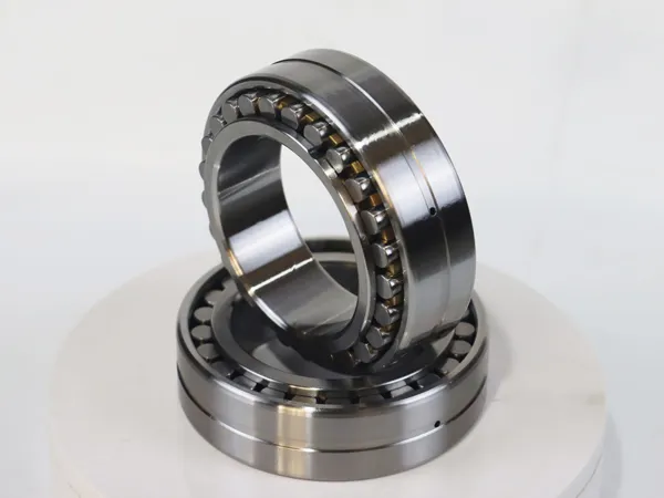
Tapered roller bearings are a type of rolling element bearing commonly used in various applications, particularly in machinery and automotive systems. These bearings are designed to handle both radial and axial loads, providing support for rotating shafts in one direction.

Tapered roller bearings consist of inner and outer rings with tapered raceways and tapered rollers. The rollers are guided by the inner ring back-face rib and the outer ring front-face rib. The angle of the taper allows the bearings to handle both radial and axial loads.

Tapered roller bearings Introduction

Tapered roller bearings

Tapered roller bearings Features

Tapered Design: Tapered roller bearings are named for their cone-shaped rolling elements, which are tapered towards the ends.

High Load Capacity: They can support both radial and axial loads, making them suitable for applications with combined loading conditions.

Efficient at Handling Thrust Loads: The tapered design allows for effective handling of thrust (axial) loads in one direction.

Durability: Typically made from high-quality steel, providing durability and resistance to wear.

Precise Manufacturing: Precision manufacturing ensures consistent performance and long life.

Tapered roller bearings Performance

Reduced Friction: Tapered rollers reduce friction during rotation, leading to higher efficiency.

Temperature Stability: They can operate under a wide range of temperatures, making them suitable for various environments.

Low Noise: Properly lubricated and maintained tapered roller bearings operate with low noise levels.

Tapered roller bearings Working Principle

Load Distribution: Tapered roller bearings distribute loads over a larger surface area, reducing stress on individual components.

Rolling Motion: As the inner and outer rings rotate, the tapered rollers facilitate smooth rolling motion.

Axial Displacement: Tapered design allows for axial displacement, accommodating thermal expansion or contraction.

For more detailed information about crossed tapered roller bearings, please click here: https://www.prsbearings.com/a/news/introduction-to-tapered-roller-bearings.html