Household furniture encompasses a wide range of items designed for use in homes to facilitate various activities, provide comfort, and enhance aesthetics.

Household furniture typically possesses a variety of features designed to fulfill functional, aesthetic, and practical requirements within a home. Here are some common features of household furniture:

Household furniture

Functionality: Furniture is designed with specific functions in mind, such as seating, sleeping, storage, dining, or working. Each piece is crafted to serve its intended purpose effectively.

Comfort: Comfort is a key consideration, especially for seating and bedding furniture. Ergonomic designs, cushioning, upholstery materials, and adjustable features contribute to comfort levels.

Durability: Well-made furniture is constructed from sturdy materials such as hardwoods, metals, or high-quality composites to withstand daily use and last for years.

Aesthetics: Furniture contributes to the overall aesthetics of a home. Design elements such as shape, color, texture, and detailing are carefully considered to complement the style and decor of the space.

Versatility: Some furniture pieces offer versatility in their design or functionality. For example, modular furniture can be rearranged to suit different layouts, while storage furniture may feature adjustable shelves or compartments.

Household furniture

Space-saving: With the increasing trend of smaller living spaces, many furniture pieces are designed with space-saving features such as compact size, built-in storage, or multifunctionality.

Ease of maintenance: Furniture materials and finishes are chosen for their ease of maintenance and cleaning. Stain-resistant fabrics, durable finishes, and removable covers are common features that simplify upkeep.

Safety: Safety features are essential, especially for furniture used by children or the elderly. Rounded edges, anti-tip mechanisms, and sturdy construction help prevent accidents and injuries.

For more detailed information about the characteristics of home furniture, please click here: https://www.rff-global.com/a/news/household-furniture-features.html

A single rolling door cabinet is a type of storage cabinet designed with a single door that rolls horizontally to open and close. These cabinets are commonly used in various settings such as offices, warehouses, garages, and workshops for storing a wide range of items including tools, equipment, files, and supplies.

Single rolling door cabinets features

Space-saving Design: Single rolling door cabinets are space-efficient since they do not require additional clearance space for the door to swing open like traditional hinged doors. This makes them suitable for use in areas with limited space or tight quarters.

Ease of Access: The rolling door mechanism allows for smooth and easy access to the contents of the cabinet. Users can slide the door horizontally to either side to open the cabinet, providing convenient access to stored items.

Single rolling door cabinets

Security: Depending on the design, single rolling door cabinets may come with locking mechanisms to secure the contents inside. This helps prevent unauthorized access and ensures the safety of valuable or sensitive items stored in the cabinet.

Durability: These cabinets are typically constructed from durable materials such as steel, aluminum, or wood, depending on the intended use and environment. This ensures the cabinet can withstand regular use and provides long-lasting durability.

For more detailed information about the characteristics of single rolling door cabinets, please click here:https://www.rff-global.com/a/news/single-rolling-door-cabinet-features.html

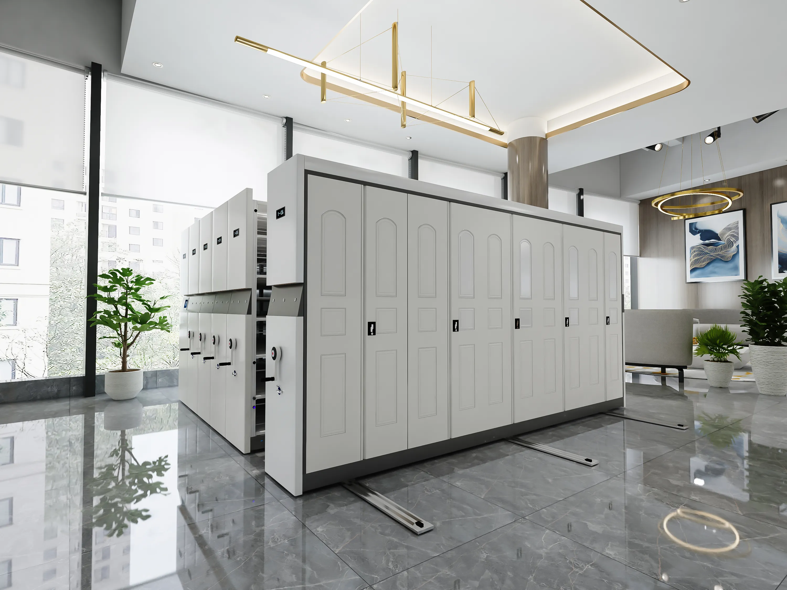
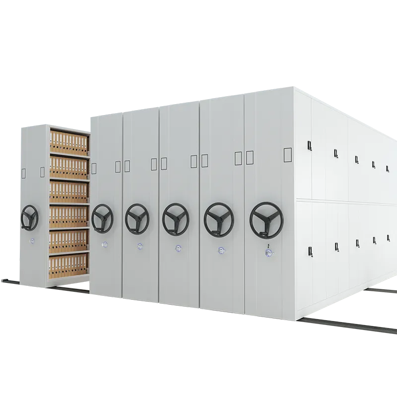
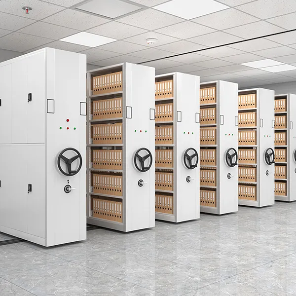
A mobile compactor, also known as a mobile compact shelving system or mobile shelving unit, is a storage solution designed to maximize space utilization by compacting shelves or racks together when not in use.

How a mobile compactor typically works

mobile compactor

Compact Design: A mobile compactor consists of multiple shelving units or racks mounted on carriages that move along tracks or rails installed on the floor. The shelving units are arranged closely together to minimize the space between them when compacted.

Movement Mechanism: The carriages of the mobile compactor are equipped with wheels or rollers that allow them to move horizontally along the tracks. The movement can be manually operated, mechanically assisted, or motorized, depending on the design and configuration of the system.

Control System: Mobile compactors are typically equipped with control mechanisms, such as handles, cranks, levers, or electronic controls, to move the carriages and access the shelves. Users can engage the control system to open or close aisles between the shelving units as needed.

Compaction Process: When a user wants to access a particular aisle or shelving unit, they engage the control mechanism to move the carriages apart, creating an open aisle for access. The remaining shelving units are compacted closely together to maximize space utilization.

Accessing Items: Once the desired aisle is created, users can easily access the stored items on the shelves. They can retrieve or store items as needed, taking advantage of the improved accessibility and organization provided by the mobile compactor system.

mobile compactor

Safety Features: Mobile compactors often incorporate safety features to prevent accidents and injuries. These may include aisle-end safety barriers, anti-tip devices, overload protection, and warning signs or signals to alert users when shelves are in motion.

For more detailed information on how the mobile compactors works, please click here: https://www.rff-global.com/a/news/mobile-compactor-working-principle.html

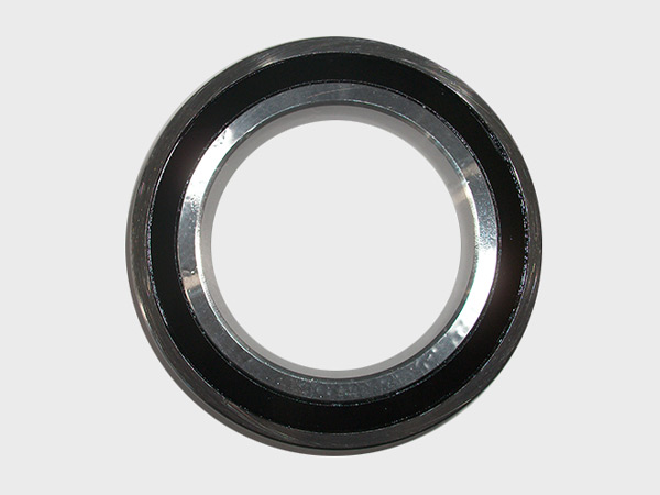
An angular contact bearing arrangement refers to the configuration of angular contact bearings within a mechanical system. Angular contact bearings are designed to accommodate combined radial and axial loads by enabling angular movement between the inner and outer races. This arrangement allows for efficient transmission of both radial and axial forces, making angular contact bearings suitable for applications where high precision and load-carrying capacity are required.

There are several common configurations for angular contact bearing arrangements, each suited for specific applications and load conditions:

Single-Row Angular Contact Bearings

In this arrangement, a single angular contact bearing is used to support both radial and axial loads. The inner and outer races have a contact angle, typically between 15 and 40 degrees, which allows the bearing to carry axial loads in one direction while still accommodating radial loads. Single-row angular contact bearings are commonly used in applications such as machine tools, pumps, and gearboxes.

Double-Row Angular Contact Bearings

Double-row angular contact bearings consist of two rows of balls and raceways, arranged back-to-back or face-to-face. This arrangement enables the bearing to support higher axial loads and moment loads compared to single-row bearings. Double-row angular contact bearings are commonly used in applications such as automotive wheel hubs, conveyor systems, and agricultural machinery.

Tandem Arrangement

In a tandem arrangement, two single-row angular contact bearings are mounted in series, with one bearing positioned behind the other along the shaft axis. This configuration allows for increased axial stiffness and load-carrying capacity, particularly in applications with heavy axial loads or alternating axial loads in both directions.

More detailed information about angular contact ball bearing arrangement types can be found here: https://www.boyingbearing.com/en/a/news/angular-contact-ball-bearings-arrangements.html

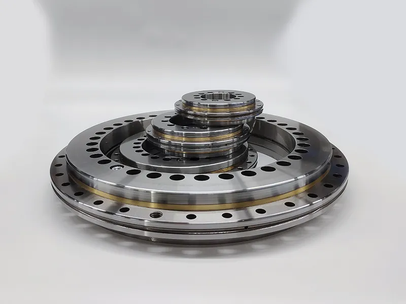
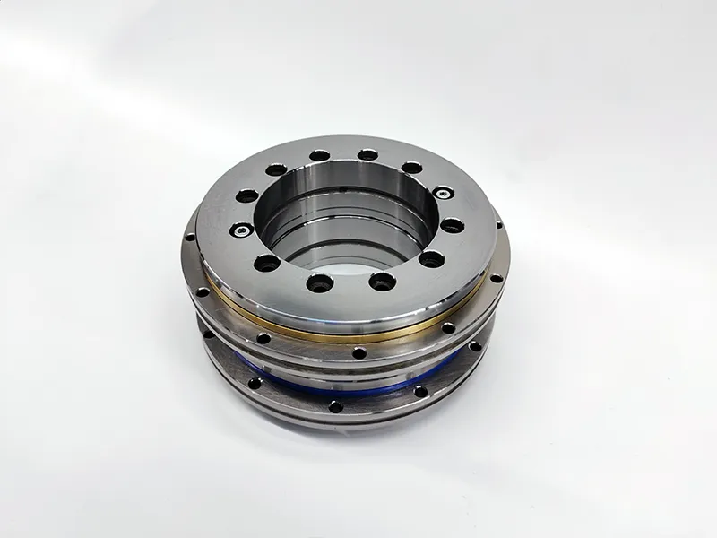
Crossed roller bearings are a type of roller bearing designed to handle both radial and axial loads simultaneously. They are known for their high load-bearing capacity, rigidity, and accuracy, making them suitable for applications where precise positioning and high load capacity are critical.

Crossed Roller Bearings Features

Construction: Crossed roller bearings consist of two sets of cylindrical rollers arranged perpendicular to each other, forming an “X” pattern when viewed from above. This crossed arrangement of rollers allows the bearing to accommodate radial, axial, and moment loads in various directions.

Crossed roller bearings

High Load Capacity: Due to their unique design, crossed roller bearings can withstand high radial, axial, and moment loads simultaneously. This makes them suitable for applications where heavy loads and high stiffness are required, such as machine tools, industrial robots, and precision equipment.

Low Friction: Crossed roller bearings typically have low friction characteristics, which result in smooth operation and reduced energy consumption. This is particularly advantageous in applications where high precision and efficiency are essential.

High Rigidity: The crossed arrangement of rollers and the precision machining of the bearing components result in high rigidity, providing excellent resistance to deformation and deflection under load. This rigidity is critical for maintaining accuracy and precision in applications such as CNC machining centers and robotics.

For more detailed information about the features of crossed roller bearings, please click here: https://www.boyingbearing.com/en/a/news/crossed-roller-bearings-features.html

Thin section bearings, also known as slim bearings or thin-walled bearings, are characterized by their compact design and thin cross-section relative to their bore diameter. They are often used in applications where space is limited and weight reduction is critical. The sizes of thin section bearings can vary depending on the manufacturer and the specific series or type of bearing. However, they typically follow standardized dimensions based on industry standards such as ISO (International Organization for Standardization) or ANSI (American National Standards Institute).

Here are some common sizes of thin section bearings, typically specified by their bore diameter, outer diameter, and width:

Thin section bearings

1 inch Series: These bearings have a bore diameter ranging from 1 inch to 2.5 inches, with outer diameters typically ranging from around 1.5 inches to 3 inches.

1.5 inch Series: These bearings have a bore diameter ranging from 1.5 inches to 3 inches, with outer diameters typically ranging from around 2 inches to 3.5 inches.

2 inch Series: These bearings have a bore diameter ranging from 2 inches to 4 inches, with outer diameters typically ranging from around 2.5 inches to 4.5 inches.

3 inch Series: These bearings have a bore diameter ranging from 3 inches to 5 inches, with outer diameters typically ranging from around 3.5 inches to 5.5 inches.

For more detailed information about the sizes of thin section bearings, please click here:https://www.boyingbearing.com/en/a/news/thin-section-bearing-sizes.html

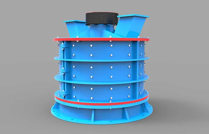
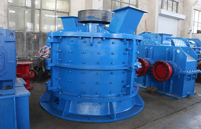
Compound crushers, also known as composite crushers or combination crushers, are designed to crush materials efficiently by combining the advantages of both hammer crushers and impact crushers. They typically consist of several main components, each serving a specific function within the internal structure of the crusher.

Compound crusher internal structure

compound crusher

Main Frame: The main frame of the compound crusher provides structural support and houses the other components of the crusher. It is usually made of welded steel plates or cast steel for strength and durability.

Rotor Assembly: The rotor assembly is a key component responsible for the crushing action in the compound crusher. It consists of a rotor shaft, rotor discs, and hammer bars or impact elements. The rotor rotates at high speed, impacting the material fed into the crusher chamber.

Crushing Chamber: The crushing chamber, also known as the crushing cavity or crushing chamber, is the space where the material is crushed by the rotor. It is typically lined with wear-resistant liners to protect the crusher housing from abrasion and wear.

Feed Hopper: The feed hopper is located above the crushing chamber and serves as the entry point for the material to be crushed. It allows for controlled feeding of the material into the crusher, ensuring efficient operation and preventing overloading.

compound crusher

Adjustable Discharge Opening: Compound crushers often feature an adjustable discharge opening or gap between the rotor and the crushing chamber. This allows for the adjustment of the final product size by controlling the size of the crushed material that exits the crusher.

For more detailed information about the internal structure of the compound crusher, please click here: https://www.zymining.com/en/a/news/internal-structure-of-compound-crushers.html

A briquetting press, also known as a briquette press or briquette machine, is a device used to convert various types of biomass, metal, or other materials into uniform, shaped briquettes. These briquettes are typically cylindrical in shape and can vary in size depending on the specific requirements of the application.

How does briquetting press work

briquetting press

Material Feeding: The raw material, which could be biomass (such as wood chips, sawdust, or agricultural residues), metal chips, or other types of material, is fed into the briquetting press. This can be done manually or through automated feeding systems, depending on the scale and complexity of the operation.

Compression Chamber: Inside the briquetting press, there is a compression chamber where the raw material is compacted under high pressure. This pressure is applied using a hydraulic system, mechanical system, or a combination of both.

Compression and Briquette Formation: As the raw material enters the compression chamber, it is subjected to high pressure, which compresses it into a dense mass. The pressure forces the material to bind together, forming briquettes of the desired shape and size. The shape of the briquettes can vary depending on the design of the press and any additional shaping attachments.

briquetting press

Ejection or Discharge: Once the briquettes are formed, they are ejected from the press either manually or through automated ejection systems. In some cases, the briquettes may need to be cooled or cured before they are ready for use or further processing.

More detailed information about how the briquetting machine works can be found here:https://www.zymining.com/en/a/news/how-does-briquetting-press-work.html

High pressure grinding rolls (HPGR) are commonly used in various applications in the mining and minerals processing industry, including crushing of hard and abrasive ores such as gold, copper, iron ore, and diamonds. They are also used in cement manufacturing, industrial minerals processing, and pellet feed preparation in the iron ore industry.

HPGR application fields

High pressure grinding rolls

Mineral Processing: HPGRs are extensively used in the mineral processing industry for ore grinding and liberation. They are employed in both primary and secondary grinding circuits for crushing and grinding of ores such as gold, copper, iron ore, nickel, and diamonds. HPGR technology is known to produce finer particle sizes with reduced energy consumption compared to traditional grinding mills, making it a preferred option in mineral processing operations.

Cement Industry: HPGRs are utilized in the cement industry for grinding raw materials such as limestone, clinker, and slag. They are often integrated into the grinding circuit to increase throughput, improve energy efficiency, and enhance the quality of the final cement product. HPGR technology can help reduce specific energy consumption and improve cement grinding performance, leading to cost savings and environmental benefits.

Iron Ore Pellet Feed Preparation: HPGRs are used in the iron ore pellet feed preparation process to enhance the pelletization properties of iron ore fines. By subjecting the ore to high pressure and compressive forces, HPGRs help improve the particle size distribution, increase the surface area, and enhance the binding properties of the ore fines, resulting in improved pellet quality and productivity in the pelletizing plant.

For more detailed information about the application fields of high-pressure grinding rollers, please click here: https://www.zymining.com/en/a/news/high-pressure-grinding-rolls-application.html

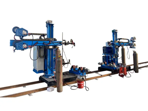
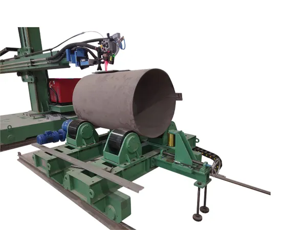
The production process of a wind tower production line involves several stages, from the manufacturing of individual components to the assembly of the complete wind tower structure.

Wind tower production line production process

Material Preparation:

Raw Materials: The main materials used in wind tower production typically include steel plates and sections. These materials are sourced from steel mills and undergo quality inspection upon arrival at the production facility.

Cutting: Steel plates and sections are cut to the required dimensions using cutting machines such as plasma or flame cutting equipment. Precise cutting ensures that the components fit together accurately during assembly.

Component Manufacturing:

Flanges and Base Plates: Flanges and base plates are fabricated from steel plates using cutting, bending, and welding processes. These components provide the foundation and attachment points for the tower sections.

wind tower production line

Tower Sections: Tower sections are manufactured by rolling and welding steel plates into cylindrical or conical shapes. Automated welding processes such as submerged arc welding (SAW) or gas metal arc welding (GMAW) are used to ensure high-quality welds.

Surface Treatment:

Shot Blasting: After fabrication, the steel components undergo shot blasting to remove any surface contaminants and improve the adhesion of protective coatings.

Priming and Painting: Primers and protective coatings are applied to the steel components to prevent corrosion and ensure long-term durability, especially in harsh outdoor environments.

Tower Assembly:

Tower Segments: The tower sections are assembled by welding them together using specialized welding equipment and techniques. Welding parameters are carefully controlled to meet stringent quality standards and ensure structural integrity.

For more detailed information on the production process of the wind tower production line, please click here: https://www.bota-weld.com/en/a/news/wind-tower-production-line-production-process.html