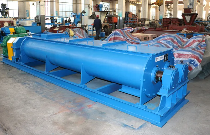
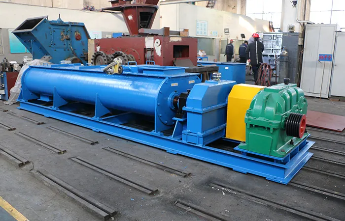
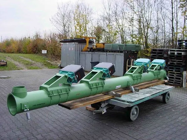
Hammer crushers are used in a variety of industries for crushing and grinding materials. They come in different models and sizes, each designed for specific applications and capacities. Here’s a comprehensive list of common models and categories of hammer crushers:

Hammer crusher model

hammer crusher

Reversible Hammer Crusher

Allows the rotor to be reversed, extending the life of the hammers and crushing plates.

Non-Reversible Hammer Crusher

The rotor can only turn in one direction, often used for primary crushing.

Heavy Hammer Crusher

Designed for large-scale, high-capacity crushing applications.

Single-Stage Hammer Crusher

Capable of crushing materials in one stage, reducing them to the desired size without the need for secondary crushing.

Double-Rotor Hammer Crusher

Equipped with two rotors, providing higher crushing efficiency and capacity.

Common Models of Hammer Crushers

Hammer crushers

Models by Specific Application

Primary Hammer Crusher

Designed for initial crushing of large materials.

Models: PCD Series (e.g., PCD0808, PCD1010, PCD1212)

For more detailed information about hammer crusher models, please click here: https://www.zymining.com/en/a/news/hammer-crusher-model.html

An impact crusher is a machine used for breaking down large rocks into smaller pieces by impacting them with the force of certain wear parts.The working principle of an impact crusher revolves around the rotor, which is a heavy-duty steel drum fitted with beaters that rotate at high speeds. The material is fed into the chamber from above and is impacted by the rotor’s centrifugal force as it rotates.

Impact crusher working principle

impact crusher

Feed Material Entry: The feed material is introduced into the crushing chamber from above, typically through a feed chute or hopper. The material may be fed directly into the center of the rotor or distributed across the width of the rotor.

Rotor and Beaters: The rotor is the central component of the impact crusher and is typically mounted horizontally. It is equipped with a series of beaters or hammers that are attached to the rotor’s circumference. These beaters are free to swing or pivot on the rotor shaft.

Impact Crushing: As the rotor rotates at high speeds, the centrifugal force generated by the rotation causes the beaters to swing outward and impact the incoming feed material. This impact crushes the material against the stationary anvils or breaker plates located within the crushing chamber.

Crushing Chamber: The crushing chamber is the area where the impact takes place. It is typically lined with durable materials such as manganese steel or high-chrome iron to withstand the high impact forces generated during crushing.

For more detailed information about the working principle of impact crusher, please click to visit: https://www.zymining.com/en/a/news/impact-crusher-working-principle.html

The production process of a wind tower welding production line involves several key stages, each requiring precision and advanced machinery to ensure the structural integrity and performance of the wind tower. Here’s an overview of the typical production process:

Wind tower welding production line production process

Wind tower welding production line

1. Material Preparation

Plate Cutting: Steel plates are cut to the required size using CNC plasma or laser cutting machines. This ensures high precision and minimizes material wastage.

Edge Preparation: The edges of the cut plates are beveled to prepare them for welding. This can be done using milling or grinding machines.

2. Rolling

Plate Rolling: The beveled plates are fed into a rolling machine to form cylindrical or conical sections. This process involves passing the plates through a series of rollers that gradually bend the plate into the desired shape.

3. Fit-Up and Tack Welding

Section Fit-Up: The rolled sections are aligned and fitted together using fit-up rotators or positioning equipment to ensure proper alignment.

Tack Welding: Initial tack welds are made to hold the sections in place. This step is critical to maintaining alignment during subsequent welding processes.

4. Main Welding

Seam Welding: The main longitudinal and circumferential welds are made using automatic or semi-automatic welding machines. Common welding methods include submerged arc welding (SAW), gas metal arc welding (GMAW/MIG), and flux-cored arc welding (FCAW).

Inspection and NDT: Non-destructive testing (NDT) methods such as ultrasonic testing (UT), radiographic testing (RT), or magnetic particle testing (MT) are performed to check for weld defects and ensure weld quality.

For more detailed information about the production process of the wind tower welding production line, please click here:https://www.bota-weld.com/en/a/news/wind-tower-welding-production-line-production-process.html

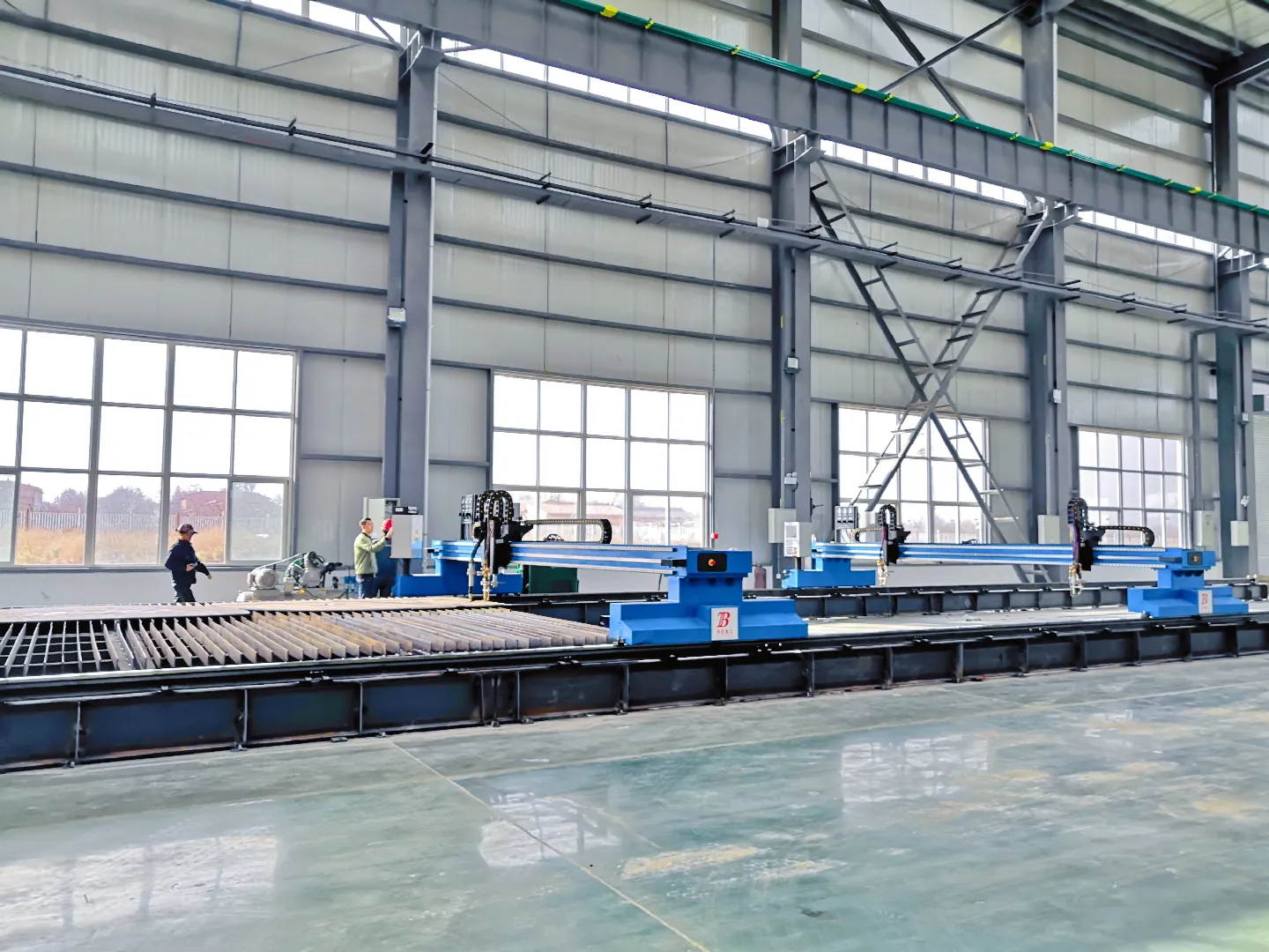
A gantry CNC cutting machine, also known as a gantry CNC plasma cutting machine or gantry CNC router, is a type of computer numerical control (CNC) machine used for precision cutting and machining of various materials. Here are the key components and features of a gantry CNC cutting machine:

Gantry CNC cutting machine composition

gantry CNC cutting machine

Gantry Structure: The gantry refers to the overhead structure that spans the cutting area. It typically consists of horizontal beams supported by vertical columns. The gantry moves along the length of the cutting table, providing stability and precision during the cutting process.

Cutting Table: The cutting table is the surface on which the material to be cut is placed. It is usually made of steel or aluminum and may be equipped with a grid or slats to facilitate the removal of waste material and improve airflow during cutting.

Cutting Head: The cutting head is mounted on the gantry and contains the cutting tool or torch. In the case of a plasma cutting machine, the cutting head houses the plasma torch, which generates a high-temperature plasma arc to melt and cut through metal. For CNC routers, the cutting head may include a spindle or router bit for milling, engraving, or carving operations.

CNC Controller: The CNC controller is the brain of the machine, responsible for interpreting the cutting program and sending commands to the motors and actuators that control the movement of the gantry and cutting head. It typically consists of a computer with specialized software for generating toolpaths and G-code instructions.

For more detailed information about the composition of the gantry CNC cutting machine, please click to visit: https://www.bota-weld.com/en/a/news/gantry-cnc-cutting-machine-composition.html

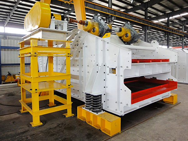
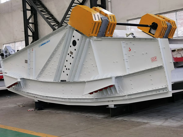
A vibrating screen is a mechanical device used for separating, sifting, and sorting materials in various industries such as mining, construction, agriculture, and recycling. The primary function of a vibrating screen is to classify materials by size, separating smaller particles from larger ones. Here’s an overview of how a vibrating screen works:

Working principle of vibrating screen

Vibrating screen

Basic Working Principle

A vibrating screen operates based on a simple principle: it uses a motor or other mechanical device to generate vibrations, which are transmitted to the screen surface. These vibrations cause the material on the screen to move and be sorted into different sizes.

Components and Mechanism

Screen Surface:

The screen surface is typically made of woven wire mesh, perforated plate, or other materials. It has openings of specific sizes to allow smaller particles to pass through while retaining larger particles on the surface.

Vibration Generator:

The vibration generator can be an electric motor, an eccentric shaft, or other devices that create mechanical vibrations. It is attached to the screen frame and induces the vibrating motion.

Screen Frame:

The screen frame holds the screen surface and supports the vibrating mechanism. It is usually constructed from sturdy materials to withstand the vibrations and the weight of the materials being processed.

Damping System:

The damping system consists of springs or rubber mounts that absorb the vibrations and prevent them from being transmitted to the supporting structure or other equipment.

Drive System:

The drive system includes the motor and the transmission mechanisms (belts, pulleys, gears) that transfer power from the motor to the vibration generator.

Operational Process

Feeding:

Material to be screened is fed onto the screen surface, typically from a hopper or conveyor.

Vibration:

The vibration generator creates oscillatory movements in the screen surface. The amplitude and frequency of the vibrations can be adjusted to suit the material and desired separation.

Screening:

As the material moves across the vibrating screen, particles smaller than the screen openings fall through and are collected underneath. Larger particles continue to move across the screen surface until they are discharged from the end.

Separation:

The screened material is separated into different size fractions. Multiple screen layers (decks) can be used for more precise sorting, with each layer having different sized openings.

For more detailed information about the working principle of vibrating screens, please click here:https://www.zexciter.com/en/a/news/vibrating-screen-working-principle.html

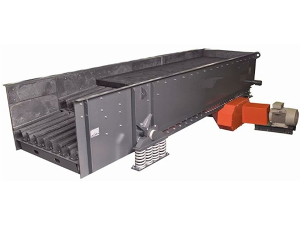
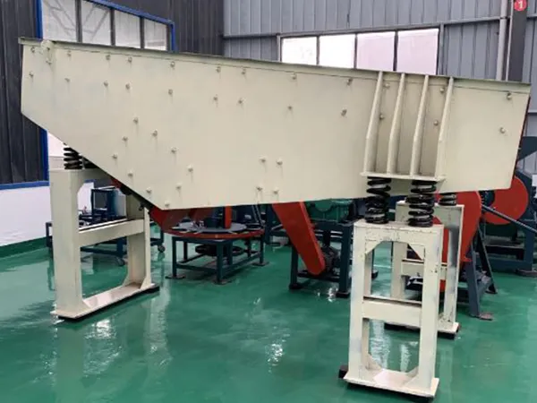
A vibrating feeder is a device used to transport materials along a production line or into processing machinery. Its primary function is to move materials in a controlled manner, ensuring a steady flow of material to downstream processes. The working principle of a vibrating feeder involves the following key components and processes.

Vibrating feeder working principle

vibrating feeder

Vibrating Drive: The vibrating feeder is equipped with an electric motor or electromagnetic drive system that generates vibrations. These vibrations cause the feeder’s trough or tray to oscillate back and forth in a linear motion.

Trough or Tray: The material to be conveyed is placed on the feeder’s trough or tray. This trough or tray is typically made of metal or other sturdy materials and is designed to withstand the weight and impact of the materials being transported.

For more detailed information about the working principle of vibrating feeder, please click to visit:https://www.zexciter.com/en/a/news/vibrating-feeder-working-principle.html

A glass tempering furnace is a complex system designed to heat-treat glass to improve its strength and safety characteristics. The tempering process involves heating the glass to a high temperature and then rapidly cooling it. This process requires several integrated systems to ensure precise control and consistent quality. Here are the main systems that a glass tempering furnace typically consists of:

Glass tempering furnace system composition

glass tempering furnace

1. Heating System

Furnace Chamber: The main body where the glass is heated. It is insulated to retain heat and ensure uniform temperature distribution.

Heating Elements: These can be electric (resistance heating elements) or gas-fired burners, providing the necessary heat to bring the glass to the tempering temperature, typically around 620-700°C (1148-1292°F).

Temperature Control: Thermocouples and sensors monitor the temperature inside the furnace. A control system adjusts the power to the heating elements to maintain the desired temperature profile.

2. Quenching System

Air Blowers: High-power fans that force air onto the heated glass to cool it rapidly. This rapid cooling is critical to developing the tempered glass’s strength properties.

Air Distribution System: Includes nozzles and ducts that direct the air flow uniformly over the surface of the glass. The design ensures even cooling to prevent stress imbalances and potential breakage.

Cooling Control: Adjusts the air pressure and flow rates to achieve the desired cooling rate and ensures uniform tempering across the glass surface.

3. Conveying System

Roller Conveyor: A system of heat-resistant rollers that transport the glass through the furnace. These rollers are designed to handle high temperatures without deforming.

For more detailed information about the composition of the glass tempering furnace system, please click here: https://www.shencglass.com/en/a/news/glass-tempering-furnace-system-composition.html

Glass tempering furnaces are specialized equipment used in the manufacturing process to strengthen glass, making it more durable and resistant to breakage. Here are some common features you might find in a glass tempering furnace.

Glass tempering furnace features

Glass tempering furnaces

Heating Elements: Furnaces typically have electric or gas heating elements designed to raise the temperature of the glass to its softening point.

Conveyor System: A conveyor belt or rollers are used to transport the glass through the furnace. The speed of the conveyor can be adjusted to control the tempering process.

Quenching System: After the glass has been heated to its softening point, it is rapidly cooled using jets of air or other cooling agents. This rapid cooling creates compressive stress on the surface of the glass, increasing its strength.

Control System: Modern furnaces are equipped with sophisticated control systems that allow operators to precisely control parameters such as temperature, conveyor speed, and quenching pressure.

Safety Features: Furnaces are equipped with safety interlocks and sensors to ensure safe operation. These may include temperature sensors, emergency stop buttons, and safety gates.

Energy Efficiency: Many modern furnaces are designed with energy-saving features such as insulated chambers and efficient heating elements to reduce energy consumption and operating costs.

Glass tempering furnaces

Capacity: Furnaces come in a range of sizes to accommodate different sizes and thicknesses of glass. Larger furnaces are capable of tempering large sheets of glass used in architectural applications, while smaller furnaces are used for smaller glass products such as automotive windows or household appliances.

For more detailed information about the features of glass tempering furnace, please click to visit: https://www.shencglass.com/en/a/news/glass-tempering-furnace-features.html

An instrument steel cabinet is a storage unit typically made from steel, designed to securely hold and organize various instruments, tools, or equipment. These cabinets are widely used in various settings, such as laboratories, workshops, industrial environments, and healthcare facilities. Here are some key features and considerations regarding instrument steel cabinets:

Key Features

steel instrument cabinets

Material: Constructed from high-quality steel, providing durability and resistance to wear, corrosion, and impacts.

Security: Often equipped with locks to secure valuable or sensitive instruments, preventing unauthorized access.

Storage Options: Available with different configurations of shelves, drawers, and compartments to accommodate a variety of tools and instruments.

Customization: Many cabinets offer customizable interior layouts to suit specific storage needs.

Mobility: Some models come with wheels or casters for easy relocation within a workspace.

Ventilation: Certain cabinets include ventilation options to keep stored items in optimal condition, particularly for instruments that require air circulation.

Labeling: Features like label holders or color-coded drawers can help with organization and quick identification of contents.

Applications

steel instrument cabinets

Laboratories: For storing scientific instruments, chemicals, and laboratory supplies.

Workshops: Ideal for organizing hand tools, power tools, and other equipment.

Healthcare: Used to store medical instruments, supplies, and pharmaceuticals securely.

Industrial: Suitable for keeping maintenance tools, safety gear, and other industrial equipment.

For more detailed information about steel instrument cabinets, please click here: https://www.cydfurniture.com/en/a/news/introduction-to-steel-instrument-cabinets.html

Gun cabinets serve several important functions, primarily focused on safety, security, and organization for firearms owners. Here are the key functions of gun cabinets:

Gun cabinet functions

Gun cabinets

Safety: Gun cabinets provide a secure storage solution for firearms, helping to prevent unauthorized access and handling, particularly by children or individuals who are not trained in firearm safety. Properly stored firearms reduce the risk of accidents, injuries, or misuse.

Security: Gun cabinets are designed to deter theft and unauthorized access to firearms. They typically feature robust construction and locking mechanisms to prevent tampering or forced entry. Some gun cabinets also come with additional security features such as biometric locks, digital keypad locks, or combination locks for added protection.

Compliance: In many jurisdictions, gun owners are required by law to store their firearms securely when not in use. Gun cabinets help firearm owners comply with these regulations by providing a safe and secure storage option that meets legal requirements.

Gun cabinets

Organization: Gun cabinets allow firearm owners to organize their firearms and related accessories in an orderly manner. Most gun cabinets feature shelves, racks, or compartments designed to accommodate firearms of various sizes and types, as well as ammunition, cleaning supplies, and other accessories.

For more detailed information about the gun cabinet functions, please click here: https://www.cydfurniture.com/en/a/news/gun-cabinet-functions.html