The integration of miniaturized, high-precision components is a defining characteristic of modern medical device engineering. Among these critical components, thin-section bearings have emerged as a preferred solution for applications ranging from surgical robotics to diagnostic imaging systems. With their unique geometry—where the cross-section remains constant regardless of bore diameter—these bearings offer distinct advantages that directly impact device performance, patient safety, and operational longevity. This article explores the five key benefits of using thin-section bearings in medical devices, providing engineers and procurement professionals with the technical rationale needed to make informed design decisions. As a trusted manufacturer, BIBO Bearing delivers high-quality thin-section bearings engineered to meet the stringent demands of the medical industry.
1. Space and Weight Optimization for Compact Designs
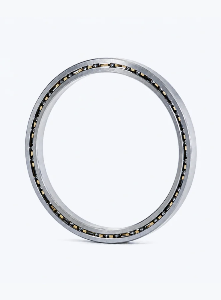
The most immediate benefit of thin-section bearings is their remarkable ability to save space and reduce weight. Unlike standard bearings that increase in cross-sectional size as the bore diameter grows, thin-section bearings maintain a fixed, slender profile—typically ranging from 3 mm to 13 mm. This characteristic allows medical device designers to create smaller, lighter, and more ergonomic equipment.
Enabling Miniaturization of Surgical Tools
In robotic surgical systems and handheld instruments, every millimeter of space matters. Thin-section bearings enable designers to place bearings directly into compact joints and articulation points without increasing the overall footprint. This facilitates smoother motion while keeping the tool lightweight for enhanced surgeon dexterity.
Impact on Portable Diagnostic Devices
Portable ultrasound scanners, patient monitors, and handheld imaging devices benefit from the reduced weight of thin-section bearings. By eliminating unnecessary bulk, these bearings contribute to easier handling and longer battery life, both critical in clinical and field settings.
2. Exceptional Precision and Smooth Operation
Medical devices demand ultra-smooth motion with minimal runout and vibration. Thin-section bearings are manufactured with high-grade steel or ceramic materials and tight tolerances (often ABEC 7 or higher) to ensure excellent rotational accuracy. This precision is vital for applications where even micron-level deviation can affect diagnostic results or surgical outcomes.
Application in CT Gantries and MRI Systems
Imaging equipment such as CT scanners require bearings that can support heavy rotating loads while maintaining concentricity. Thin-section bearings reduce the gap between the rotating and stationary parts, allowing for higher resolution imaging with less artifact. BIBO Bearing offers customized thin-section bearings with optimized raceway geometries for such demanding environments.
Consistent Performance Over Extended Cycles
Thanks to advanced heat treatment and precision grinding, thin-section bearings exhibit consistent torque and low noise over millions of cycles. This reliability is essential for infusion pumps, ventilators, and other life-sustaining devices that operate continuously.
…
For more detailed information on the five main advantages of using thin-section bearings in medical devices, please click to visit:https://www.bobibearing.com/a/bearing-knowledge/using-thin-section-bearing.html