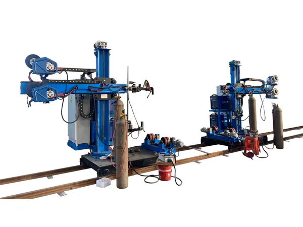
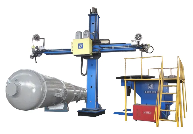
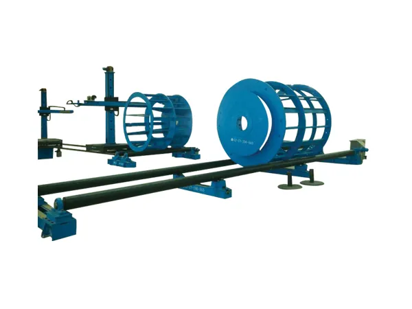
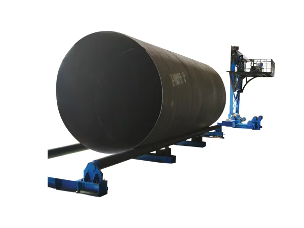
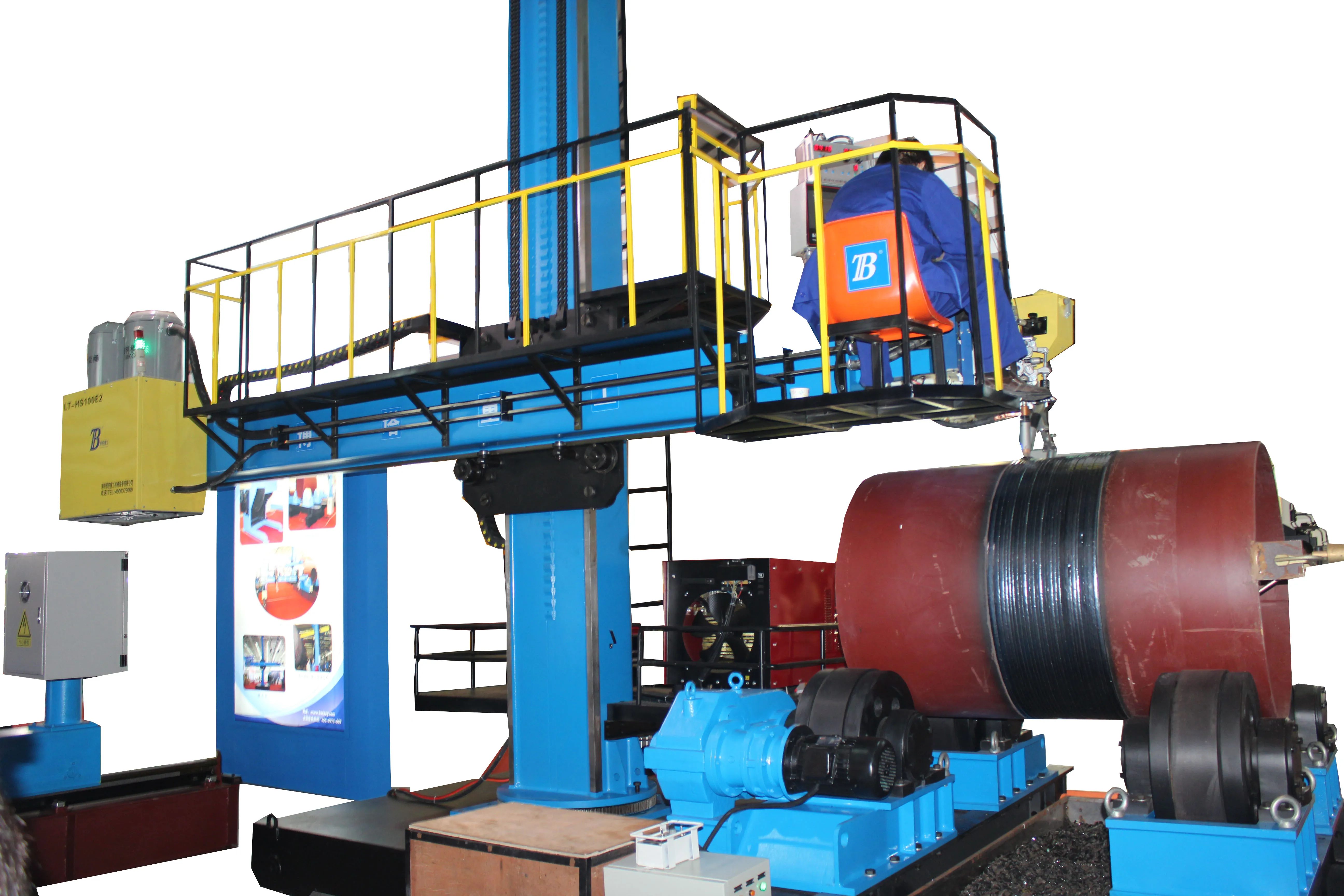
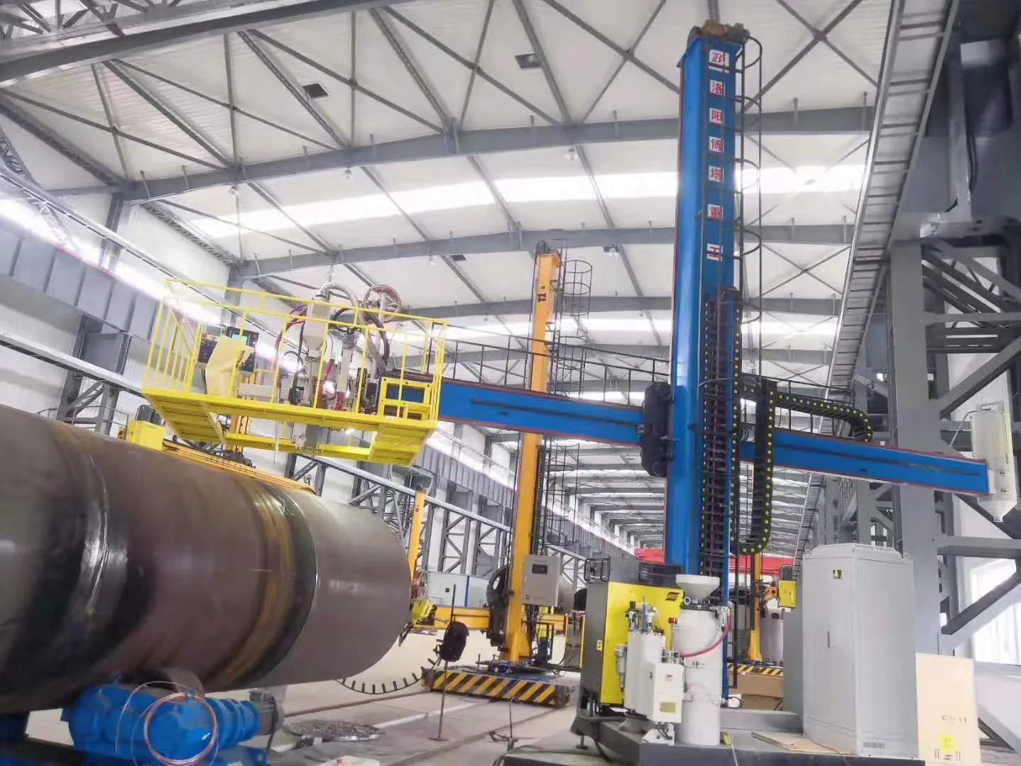
A storage tank welding production line is a specialized setup designed for the efficient manufacturing of storage tanks used in various industries, such as oil and gas, chemicals, water treatment, and food processing.

Key Components of Storage Tank Welding Production Line

Storage Tank Welding Production Line

Raw Material Preparation:

Sheets of steel or other materials are cut to size and prepared for welding.

Welding Stations:

Automated or semi-automated welding machines perform various types of welding (e.g., TIG, MIG, or submerged arc) to join tank components.

Assembly Line:

Components are assembled in a sequential manner to streamline production.

Inspection Stations:

Quality control measures, including visual inspection and non-destructive testing, ensure weld integrity and overall quality.

Finishing Area:

Tanks are finished through processes such as grinding, painting, or coating to enhance durability and corrosion resistance.

Storage and Logistics:

Finished tanks are stored or transported for installation or further processing.

Storage Tank Welding Production Line Production Process

Storage Tank Welding Production Line

Design and Planning:

Detailed plans are developed, often using CAD software, to specify dimensions and material requirements.

For more detailed information about the process flow of the tank welding production line, please click here: https://www.bota-weld.com/en/a/news/storage-tank-welding-production-line-process.html

A gantry CNC (Computer Numerical Control) welding machine is a type of automated welding system designed for high precision and efficiency in welding operations. These machines are commonly used in industries such as automotive, aerospace, shipbuilding, and heavy machinery manufacturing.

Gantry CNC welding machine components

Gantry CNC welding machine

Gantry Frame:

The main structural component that moves the welding head along the X and Y axes.

Built from strong materials to withstand the forces and heat generated during welding.

CNC Controller:

The brain of the machine that controls all movements and welding parameters.

Can be programmed with specific welding paths and parameters for different jobs.

Welding Power Source:

Supplies the electrical energy needed for the welding process.

Can be adjusted to different power levels based on the welding requirements.

Welding Head/Torch:

The tool that performs the welding operation.

Can be equipped with different types of welding torches depending on the application.

Drive System:

Includes motors, drives, and transmission systems that move the gantry and welding head.

Often uses servo motors for precise control.

Cooling System:

Cools the welding head and other components to prevent overheating.

Can include water cooling or air cooling systems.

For more detailed information about the composition of the gantry CNC welding machine, please click here: https://www.bota-weld.com/en/a/news/gantry-cnc-welding-machine-composition.html

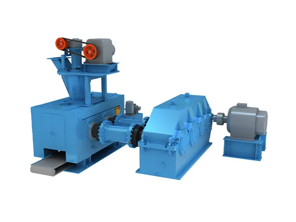
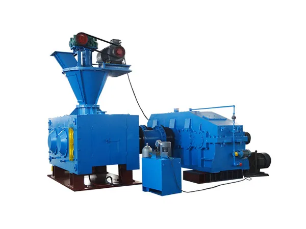
The roller skin of the briquetting machine is an important part of the briquetting machine. It is located outside the roller core of the briquetting machine. It is usually a cylindrical component with a ball socket on its surface. The shape and size of these ball sockets are designed according to the pressed material and the required product shape. The adjustment of the roller skin of the briquetting machine is a key step to ensure the normal operation of the briquetting machine and improve the product quality.

Briquetting Machine Roller Adjustment

Briquetting Machine Roller

1. Adjustment method

Gap adjustment:

The gap of the roller skin determines the filling amount and molding pressure of the material. The appropriate gap can ensure that the material is evenly distributed between the roller skins and avoid molding problems caused by uneven pressure.

The gap between the roller skins is usually adjusted by adjusting the adjusting nut of the machine. The gap size needs to be adjusted according to the nature of the material and the molding requirements.

In general, the smaller the gap, the denser the molded balls, but too small a gap may cause the equipment to jam or block the material; too large a gap will cause the molding accuracy to decrease.

Parallelism verification:

Use tools and measuring equipment to check the parallelism of the roller skins and make fine adjustments until the two roller skins are completely parallel over the entire length. The guarantee of parallelism helps the material to be evenly stressed between the roller skins and improve the molding quality.

Pressure adjustment:

The pressure of the briquetting machine is usually achieved by adjusting the hydraulic cylinder or mechanical transmission system. The size of the pressure should be adjusted according to the nature of the material and the molding effect. Too low pressure will result in poor spherical quality, while too high pressure may increase the equipment load and energy consumption, and even damage the machine.

More detailed information about briquetting machine roller skin adjustment can be found at: https://www.zymining.com/en/a/news/briquetting-machine-roller-adjustment.html

Bucket elevator is a continuous conveying machine that uses a series of buckets evenly fixed on an endless traction member to vertically lift materials. It is widely used in many industrial fields and has a series of unique advantages and characteristics.

The working principle of bucket elevator is mainly based on the transmission of chain or belt, and the materials are lifted from low to high through a series of buckets. The following is a detailed description of the working principle:

Bucket elevator working principle

Bucket elevator

Bucket elevator is a device that uses transmission devices such as chains or belts to lift materials from low to high. Its working principle includes four main steps: loading, lifting, transmission and unloading of materials.

Specific steps

Loading:

The material is loaded into the bucket of the bucket elevator through the feed port. The bucket is the main loading component of the bucket elevator, which is responsible for loading and temporarily storing materials.

Lifting:

When the drive device (usually composed of a motor, a reducer, a coupling, etc.) is started, it generates power and transmits it to the bucket through a transmission device (chain or belt).

The bucket rises along the body driven by the transmission device, lifting the material from low to high. In this process, the chain plate or belt plays a role in stabilizing the transmission of materials and reducing material wear.

Transmission:

As the bucket rises, the material is stably transmitted to a high place. The rotation speed of the chain plate or belt is indirectly controlled by the reducer, so that the material can be kept continuous, accurate and stable during the transmission process.

Discharging:

When the hopper reaches the top, it will encounter the discharge port. At this time, the hopper will open or tilt in some way to discharge the material from the hopper, completing the lifting and transportation process.

The unloading process can be achieved through auxiliary devices such as diversion nozzles to ensure that the material is transported to the destination at a uniform speed.

Structural composition

Bucket elevator

The bucket elevator is mainly composed of the following main components:

Feeding hopper: a container for loading materials.

For more detailed information about the working principle of bucket elevator, please click here: https://www.zymining.com/en/a/news/bucket-elevator-working-principle.html

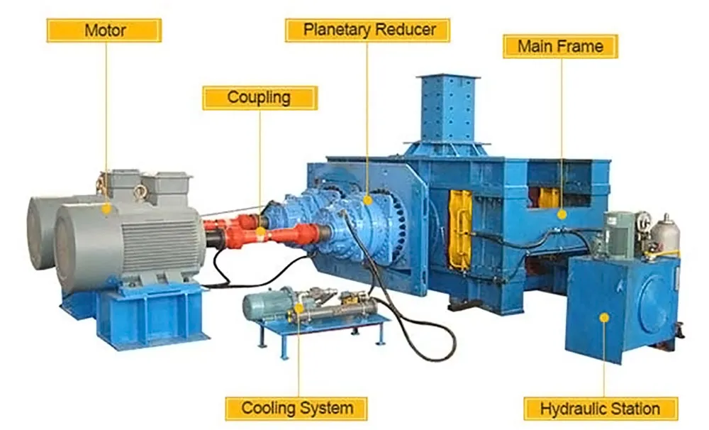
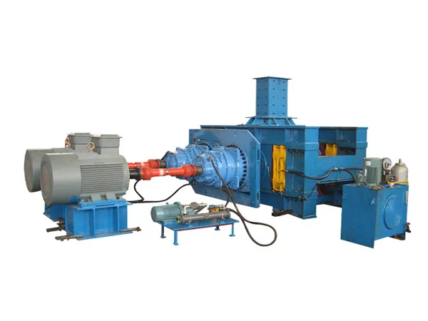
High-pressure grinding rolls is mainly used in the ore industry and is also a type of crusher. As the main equipment for crushing in the ore industry, since it is the main equipment, it will be used very frequently. All machines are inseparable from daily maintenance and overhaul. Correct maintenance and overhaul can increase the service life of the machine, and early overhaul can detect problems early, so that small problems will not become bigger, affecting normal work and causing accidents.

Common fault inspection and repair of high-pressure grinding rolls

High-pressure grinding rolls

1. If the lubrication system finds that there is no grease overflow from the labyrinth seal of the bearing seat, the following reasons may be the case:

① lack of oil;

② pipeline failure;

③ grease pump is broken. If the color and properties of the oil flowing out of the oil drain port of the non-loaded bearing seat are found to have changed, it may be that cooling water or other foreign matter has been mixed into the lubricating grease.

2. The movable roller moves irregularly in the horizontal direction. Generally, the nitrogen accumulator pressure is insufficient or damaged.

3. The hydraulic oil temperature is high. It may be: serious internal leakage in the system or the pump has been running for too long, and the hydraulic system needs to be checked.

4. The roller gap is too large. There may be the following reasons:

① Severe wear on the roller surface;

② No pressure;

③ There is material accumulation between the rollers. It needs to be handled as appropriate.

5. The roller gap is too small. It may be that there is a problem with the size of the gap block, or the position of the displacement sensor is set incorrectly.

6. The roller is stuck. It may be that there is foreign matter between the rollers, or there is too much material stored between the rollers when starting.

7. The roller does not rotate. The reasons include:

① Motor failure;

② Reducer failure.

8. The roller surface temperature is too high. It may be that the feed temperature is too high. Measures should be taken to control the upstream raw material temperature, otherwise it will affect the wear resistance of the roller surface and accelerate wear.

9. The bearing temperature is too high. The reasons include:

For more detailed information on the inspection and maintenance of high pressure grinding roller, please click here:https://www.zymining.com/en/a/news/high-pressure-grinding-rolls-inspection.html

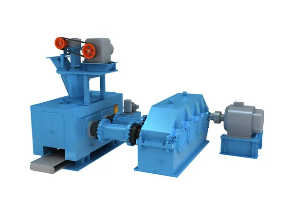
The power consumption of a high-pressure ball press machine can vary significantly depending on its size, capacity, and the specific application for which it is used. However, here are some general guidelines for the power requirements of high-pressure ball press machines.

High pressure ball press power

high-pressure ball press machine

Small to Medium-Sized Machines

Power Range: Typically between 15 kW to 55 kW (20 HP to 75 HP)

Usage: Suitable for small to medium-scale production, such as in metallurgy, chemical industry, and small manufacturing plants.

Large-Sized Machines

Power Range: Typically between 75 kW to 200 kW (100 HP to 270 HP)

Usage: Suitable for large-scale production, such as in large metallurgical plants, mining operations, and large manufacturing industries.

Factors Influencing Power Requirements

high-pressure ball press machine

Machine Capacity:

Higher capacity machines that can produce more output per hour generally require more power.

Material Properties:

Harder or denser materials require more power to compress into balls.

Pressure Requirements:

Higher pressure settings require more power to generate the necessary force.

Operational Duty Cycle:

Machines that operate continuously or under heavy-duty conditions will have higher power requirements compared to those used intermittently.

For more detailed information about the power of high pressure ball press, please click here: https://www.zymining.com/en/a/news/high-pressure-ball-press-power.html

Both roller bearings and ball bearings are rolling bearings used to reduce friction and support radial and axial loads in rotating applications. They differ significantly in several ways.

Difference Between Roller Bearings and Ball Bearings

roller bearings

1. Basic Definition and Structure

Roller bearing: It is a kind of rolling bearing and one of the widely used components in modern machinery. It relies on rolling contact between the main components to support the rotating parts. The rolling element of the roller bearing is usually cylindrical or conical, with different structural types, such as spherical roller bearings, thrust spherical roller bearings, tapered rollers and cylindrical roller bearings.

Ball bearing: It is also a kind of rolling bearing, and its rolling element is spherical, that is, the steel ball is installed between the inner and outer steel rings. The design of ball bearings enables it to withstand large loads and is widely used in various mechanical equipment.

2. Contact Mode and Load-bearing Capacity

Contact mode: The rolling element and raceway of the roller bearing are in line contact. As the load increases, the contact line will become a rectangle, and the contact area is relatively large. The rolling element and raceway of the ball bearing are in point contact. As the load increases, the contact point will become an elliptical area, and the contact area is small.

Load-bearing capacity: Due to the different contact areas, roller bearings usually have higher load-bearing capacity. Compared with ball bearings of the same size, roller bearings can withstand heavier loads, but the speed may be relatively low. Ball bearings are more suitable for low torque and high speed applications.

3. Application Characteristics

roller bearings

Roller bearings:

Applicable to occasions that need to withstand high radial and axial forces.

The starting torque is small, the rotation accuracy is high, and it is easy to select.

For more detailed information about the difference between roller bearings and ball bearings, please click here: https://www.boyingbearing.com/en/a/news/difference-between-roller-bearings-and-ball-bearings.html

The design and assembly of crossed roller bearings are key links to ensure their performance, life and stable operation of the entire mechanical system, and are also key links to ensure their normal operation and service life.

Design and Assembly of Crossed Roller Bearings

crossed roller bearings

1. Design of Crossed Roller Bearings

Structural Design

The structural design of crossed roller bearings is the basis of their performance. The bearing’s load capacity, running accuracy, friction and wear, and lubrication and sealing factors must be fully considered during design.

The cross arrangement of rollers, raceway shape, cage structure, etc. all need to be carefully calculated and optimized to ensure that the bearings can perform well under various working conditions.

Common types of crossed roller bearings include RB type (inner ring as a whole, outer ring split), RE type (inner ring split, outer ring as a whole), RU type (inner and outer ring as a whole, with mounting holes), RA type (inner ring as a whole, outer ring split, ultra-thin), etc. Each type has its specific application scenarios and advantages.

Material Selection

Material is one of the key factors that determine bearing performance. When selecting materials, it is necessary to consider its strength, hardness, wear resistance, corrosion resistance, and thermal stability.

Common materials include high carbon chromium bearing steel, stainless steel, ceramics, etc. Different materials have different performance characteristics and need to be selected according to the specific use environment and requirements of the bearing.

More detailed information on cross roller bearing design and assembly considerations can be found at: https://www.boyingbearing.com/en/a/news/design-and-assembly-of-crossed-roller-bearings.html

Harmonic reducers, also known as harmonic drive gears or strain wave gears, are precise mechanical devices used to reduce speed and increase torque in various applications. They rely on flexible elements and harmonic waves to achieve motion. Bearings are a critical component in harmonic reducers, supporting their smooth operation and long lifespan.

Harmonic reducer bearings types

Harmonic reducer bearings

Crossed Roller Bearings:

Structure: Cylindrical rollers are arranged in a crisscross pattern.

Advantages: High rigidity, high load-carrying capacity, and precision.

Applications: Often used in robotics, aerospace, and precision machinery where compact size and high accuracy are essential.

Cylindrical Roller Bearings:

Structure: Cylindrical rollers are aligned parallel to each other.

Advantages: Can handle high radial loads and moderate thrust loads.

Applications: Suitable for heavy-duty applications with high radial loads.

Angular Contact Ball Bearings:

Structure: Balls are arranged at an angle, allowing them to handle combined radial and thrust loads.

Advantages: High-speed capability, good axial and radial load support.

Applications: Commonly used in applications requiring both radial and axial load handling, such as in precision instruments and machinery.

For more detailed information about harmonic reducer bearing types, please click here: https://www.boyingbearing.com/en/a/news/harmonic-reducer-bearings-types.html

Crossed roller bearings are a type of high-precision bearing with a unique structure that allows them to support radial, axial, and moment loads simultaneously. Their structure and design offer high rigidity and compact size, making them suitable for applications requiring high accuracy and stiffness, such as robotics, machine tools, and medical equipment.

Structure of Crossed Roller Bearings

Crossed roller bearings

Inner and Outer Rings:

Inner Ring: Often split into two pieces to facilitate the insertion of the rollers and retainers.

Outer Ring: Can be one piece or split, depending on the design. The outer ring typically has a groove to house the rollers and retainers.

Rollers:

Cylindrical rollers are positioned between the inner and outer rings.

Rollers are arranged at right angles (90 degrees) to each other in an alternating pattern, which allows the bearing to handle loads from multiple directions.

Separator/Retainer:

A retainer or separator is used to keep the rollers in their correct positions and to prevent them from contacting each other.

The retainer can be made of materials like metal or plastic, ensuring smooth rotation and reduced friction.

Raceways:

Both the inner and outer rings have precisely machined raceways that match the rollers’ profiles.

The raceways ensure the rollers are guided accurately, distributing the loads evenly across the rollers.

Features and Benefits

Crossed roller bearings

High Load Capacity:

The crossed arrangement of rollers allows the bearing to support loads in all directions (radial, axial, and moment) with high capacity.

High Rigidity and Precision:

The compact design and precise manufacturing of the raceways and rollers provide high rigidity and accuracy, which is crucial for precision applications.

More detailed information about the structure of crossed roller bearings can be found at: https://www.boyingbearing.com/en/a/news/crossed-roller-bearing-structure.html